Security system annunciation communication delay

a technology of communication delay and security system, applied in the field of electronic security systems, can solve the problems of increased installation/labor cost, system vulnerability, destruction and/or disarming of notification devices,

Active Publication Date: 2011-02-17
JOHNSON CONTROLS TYCO IP HLDG LLP
View PDF6 Cites 114 Cited by
  • Summary
  • Abstract
  • Description
  • Claims
  • Application Information

AI Technical Summary

Benefits of technology

Exemplary embodiments of the present invention are directed to an apparatus and method for an electronic security system. In an exemplary embodiment, a system for transmitting alarm notifications for use with an alarm system in a monitored building includes a plurality of devices including sensors and notification devices and a main control unit that communicates with each of the plurality of sensors. The main control unit communicates with a receiver located at a central monitoring to provide alarm event notifications. A machine-readable storage medium encoded with a computer program code is included in the main control unit such that, when the computer program code is executed by a processor, the processor performs a method where event signal data is received by the control unit from at least one of the plurality of sensors and the data is processed by the main control unit. An alarm notification signal representative of the event signal is sent from the main control unit to the receiver at the central monitoring facility by the processor. Alternatively, the signal from the main control unit may be sent to an intermediary site (e.g. clearing house) that translates the signal for the receiver located at the central station. A determination is made whether the alarm

Problems solved by technology

Although these systems are reliable, they require increased installation/labor costs.
All of these systems are susceptible to the “smash and grab” intruder technique where an intruder smashes through a door and grabs the control unit before an alarm notification signal is sent to the monitoring facility and/or a signal is sent to trigger a notification device such as a siren.
However, the smash and grab technique requires the intruder to locate t

Method used


Image

  • Security system annunciation communication delay
  • Security system annunciation communication delay
  • Security system annunciation communication delay

Examples


Embodiment Construction

The present invention will now he described more fully hereinafter with reference to the accompanying drawings, in which preferred embodiments of the invention are shown. This invention, however, may he embodied in many different forms and should not be construed as limited to the embodiments set forth herein. Rather, these embodiments are provided so that this disclosure will be thorough and complete, and will fully convey the scope of the invention to those skilled in the art. In the drawings, like numbers refer to like elements throughout.

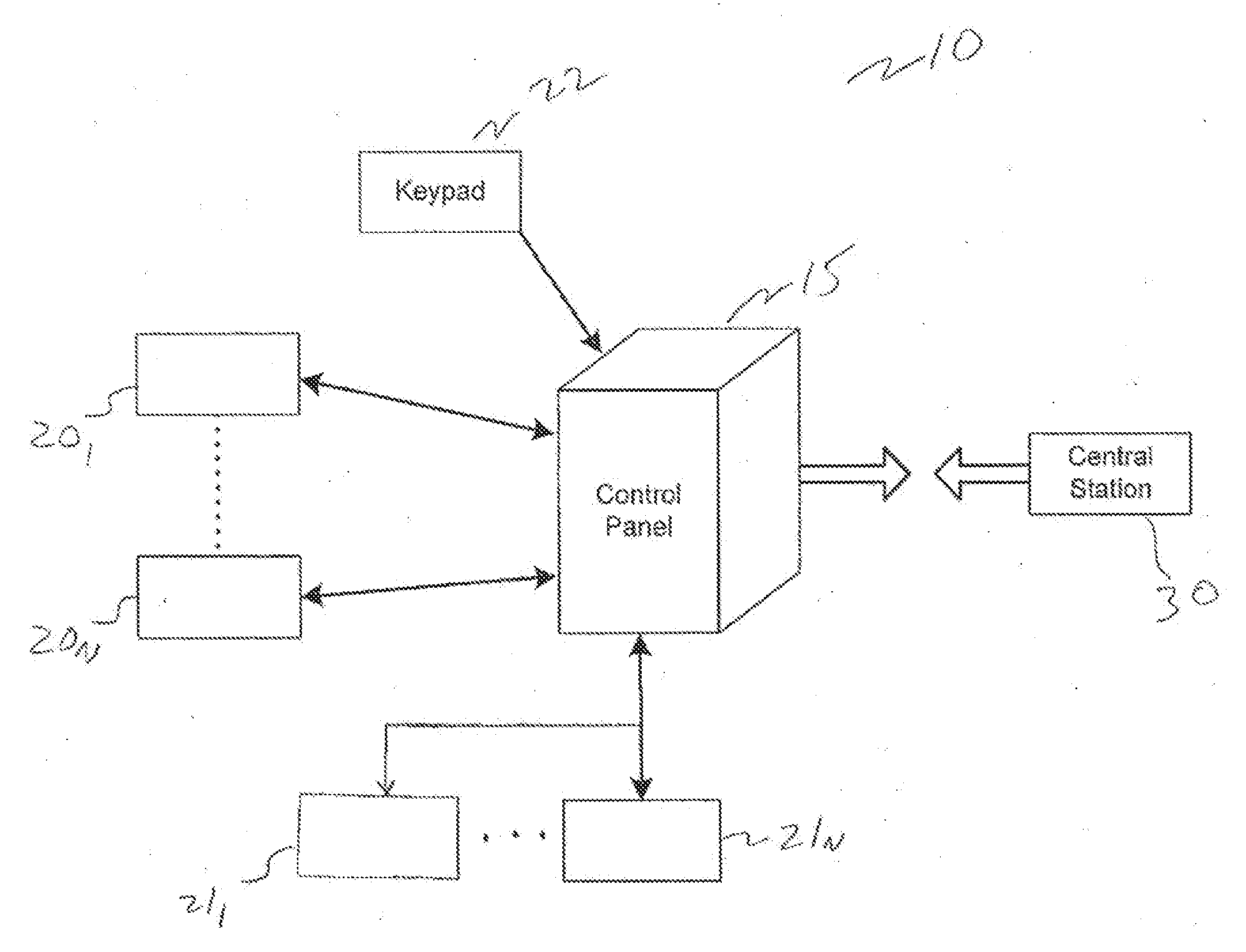
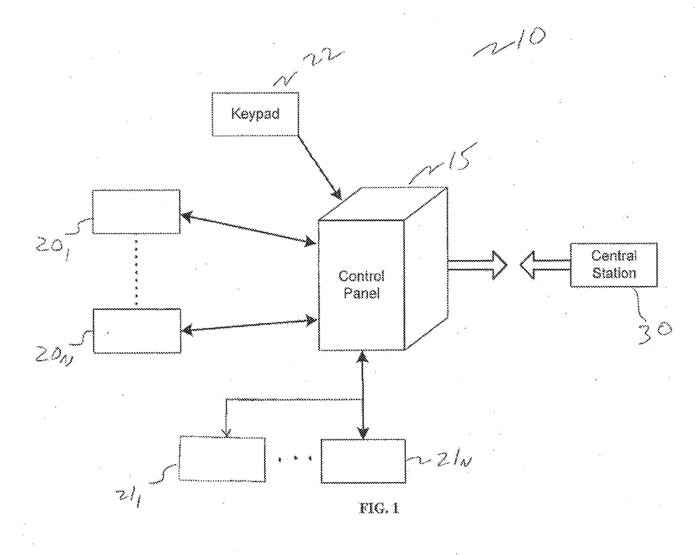
FIG. 1 is a block diagram of an exemplary security system 10 including a control panel 15, a plurality of sensor / contact devices 201-20N, annunciation devices 211-21N, for and at least one user interface 22 (e.g. keypad). A non-limiting exemplary list of such sensors / contact devices 201-20N include heat, smoke, fire and toxic gas detectors, and door, window and motion detectors. Annunciation device(s) 211-21N, may be, for example, sirens, emerge...


PUM


Abstract

A security system including a roam control unit, a plurality of sensors and a user interface device. The main control unit communicates with a remote central monitoring station, when a sensor detects an alarm event. Once the communication signal from the main control unit is successfully transmitted to the central station, a siren is sounded. Thus, the delay time to trigger the siren is dynamic based on the time it takes for successful transmission of an alarm notification to the central station. This dynamic delay accounts for transmission interruptions between the security system, and the central station and allows the location of the main unit and/or the siren from being detected prior to successful, alarm transmission, to the central station.

Description

BACKGROUND OF THE INVENTION 1. Field of the InventionEmbodiments of the invention relate to the field of electronic security systems. More particularly, the present invention relates to an apparatus and method for providing dynamic alarm notification signals within a security system.2. Discussion of Related ArtTypical building alarm systems often include a number of devices positioned throughout a building or home to alert occupants of security and fire emergencies. For example, alarm systems may typically include devices such as sensors used to monitor various conditions, such as fire, smoke, toxic gases, high / low temperature (e.g., freezing) or flooding as well as annunciation devices used to alert an occupant of these various conditions. These devices communicate, either wired or wirelessly, with an alarm panel. For example, in response to triggering a door sensor, a signal is transmitted to the alarm panel that in turn may sound or otherwise notify the occurrence of the alarm co...

Claims


Application Information

Patent Timeline
IPC IPC(8): G08B21/00
CPCG08B25/014G08B25/001
Inventor FOISY, STEPHANESTORRIE, BRIAN
Owner JOHNSON CONTROLS TYCO IP HLDG LLP
Why Eureka
Try Eureka