Battery module

a battery module and battery technology, applied in the field of batteries, can solve the problems of rechargeable batteries combusting or exploding, etc., and achieve the effect of improving safety and improving safety

Active Publication Date: 2011-02-17
ROBERT BOSCH GMBH +1
View PDF4 Cites 56 Cited by
  • Summary
  • Abstract
  • Description
  • Claims
  • Application Information

AI Technical Summary

Benefits of technology

The technical effect of this patent is improving safety by inducing a short circuit through installation of a shorting member or blocking the connection with a fuse unit to stop charging and discharging of batteries affected by abnormal conditions.

Problems solved by technology

This patent discusses how multiple rechargeable batteries can be combined into a single battery module for use in various applications like electric cars. However, if one of these batteries malfunctions and generates excessive heat or pressure, they could catch fire or explode. Therefore, the technical problem addressed in this patent is preventing damage or injury caused by malfunctioning rechargeable batteries in battery modules.

Method used


Image

  • Battery module
  • Battery module
  • Battery module

Examples


Embodiment Construction

[0038]The present invention will be described more fully hereinafter with reference to the accompanying drawings, in which some exemplary embodiments of the invention are shown. As those skilled in the art would realize, the described exemplary embodiments may be modified in various different ways, all without departing from the spirit or scope of the present invention. The drawings and description are to be regarded as illustrative in nature and not restrictive. Like reference numerals designate like elements throughout the specification.

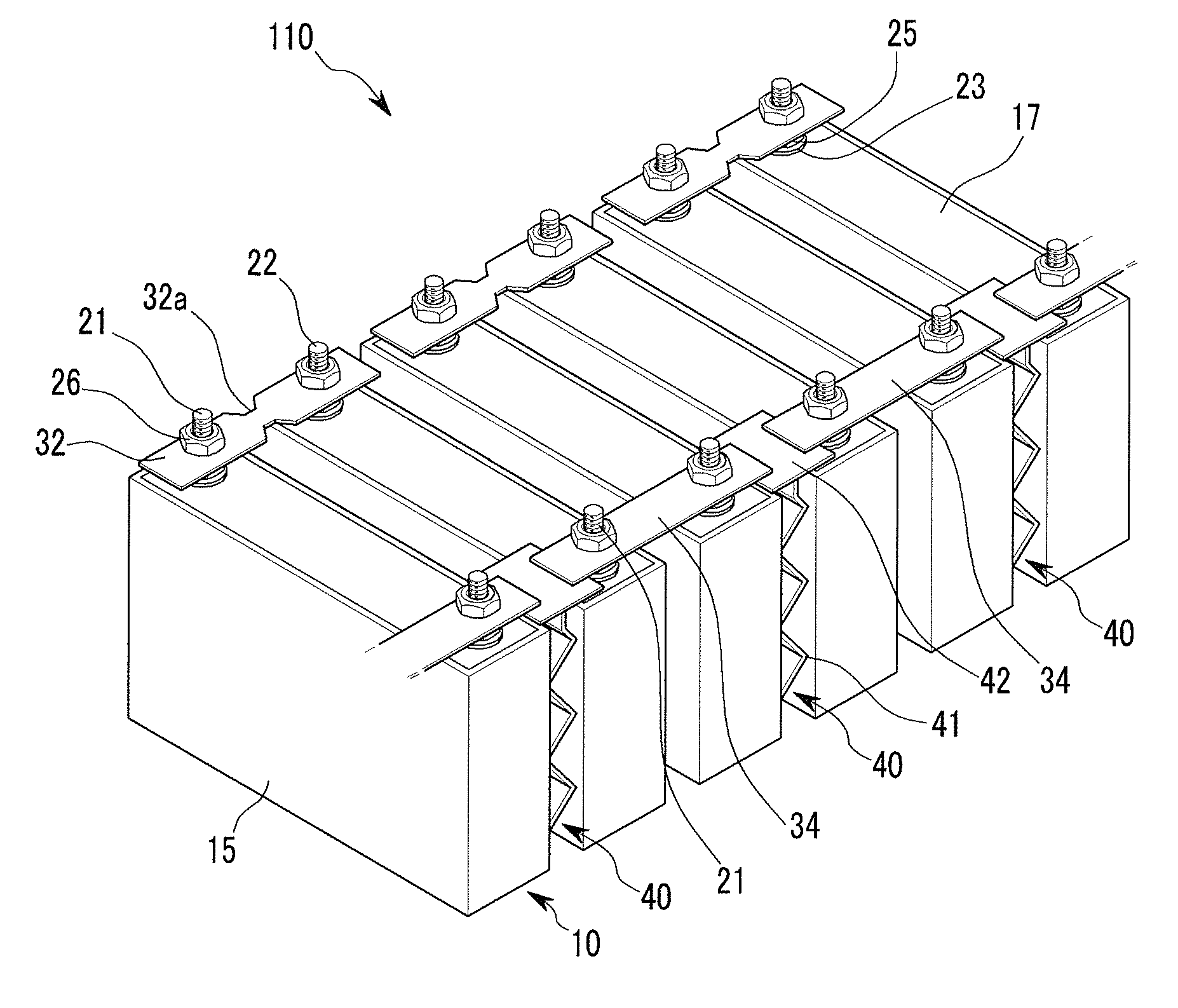
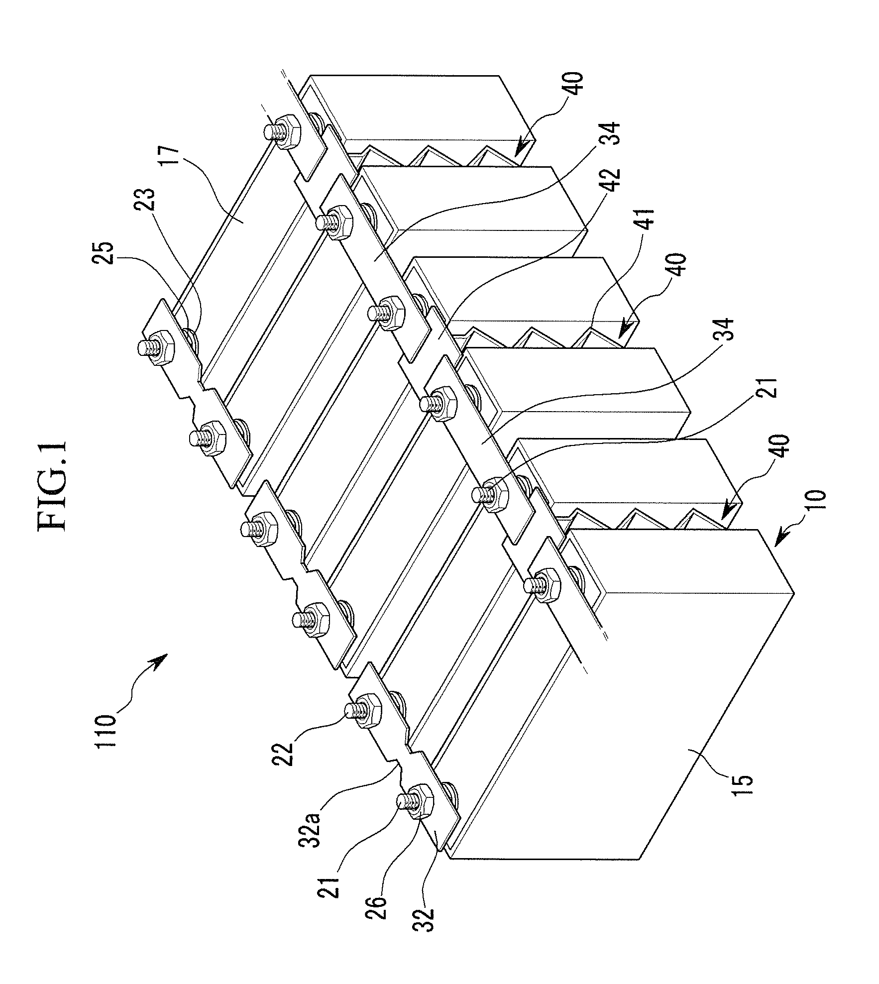
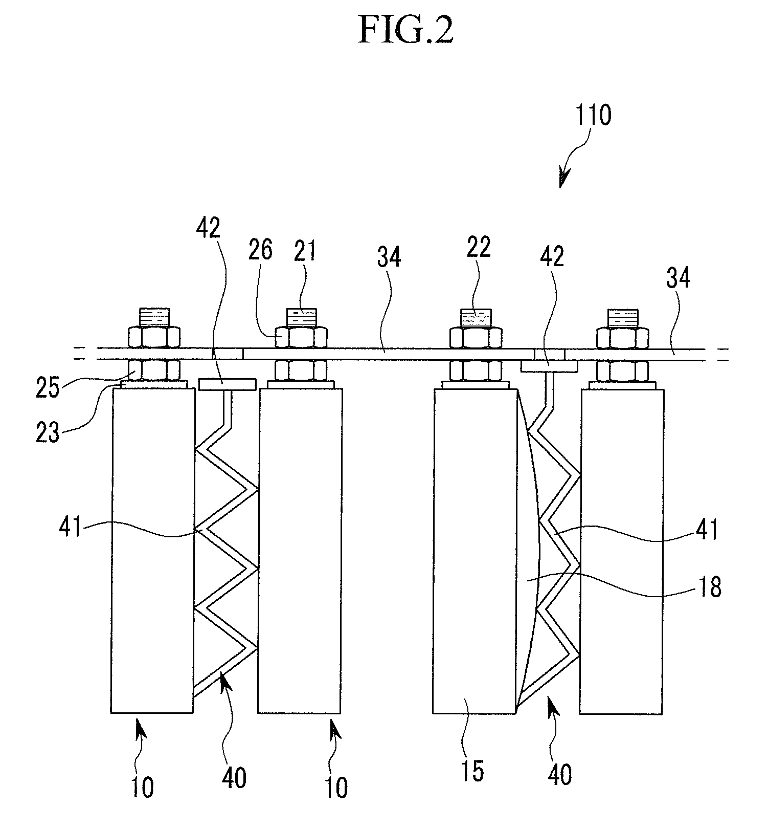
[0039]FIG. 1 is a perspective view of a battery module according to one exemplary embodiment of the present invention, and FIG. 2 is a lateral view of a portion of the battery module shown in FIG. 1.

[0040]Referring to FIG. 1 and FIG. 2, a battery module 110 according to one embodiment includes a plurality of rechargeable batteries 10 having a positive terminal 21 and a negative terminal 22, connecting members 32 and 34 electrically connecting the t...


PUM


Abstract

A battery module including a plurality of rechargeable batteries including a case and terminals protruding outside of the case; a first connecting member electrically connecting first terminals of neighboring rechargeable batteries and including a fuse unit configured to disconnect the first terminals of the neighboring rechargeable batteries when an overcurrent is generated; a plurality of second connecting members electrically connecting second terminals of the neighboring rechargeable batteries to terminals of connected rechargeable batteries; and a shorting member configured to generate a short circuit by connecting neighboring second connecting members to each other.

Description


Claims


Application Information

Patent Timeline
Owner ROBERT BOSCH GMBH
Why Eureka
Try Eureka