Apparatus and method for positioning a wireless user equipment

a wireless user and equipment technology, applied in the field of apparatus and a positioning method for wireless user equipment, can solve the problems of inaccurate positioning of user equipment, low power of neighboring base stations, multipath issues,

Active Publication Date: 2011-02-17
WSOU INVESTMENTS LLC
View PDF12 Cites 70 Cited by
  • Summary
  • Abstract
  • Description
  • Claims
  • Application Information

AI Technical Summary

Problems solved by technology

Two issues may affect accurately positioning a user equipment.
One issue may be OTDOA hearability and another issue may be multipath issue.
Due to the hearability issue, the signals from neighboring base stations are received with ve

Method used


Image

  • Apparatus and method for positioning a wireless user equipment
  • Apparatus and method for positioning a wireless user equipment
  • Apparatus and method for positioning a wireless user equipment

Examples


Embodiment Construction

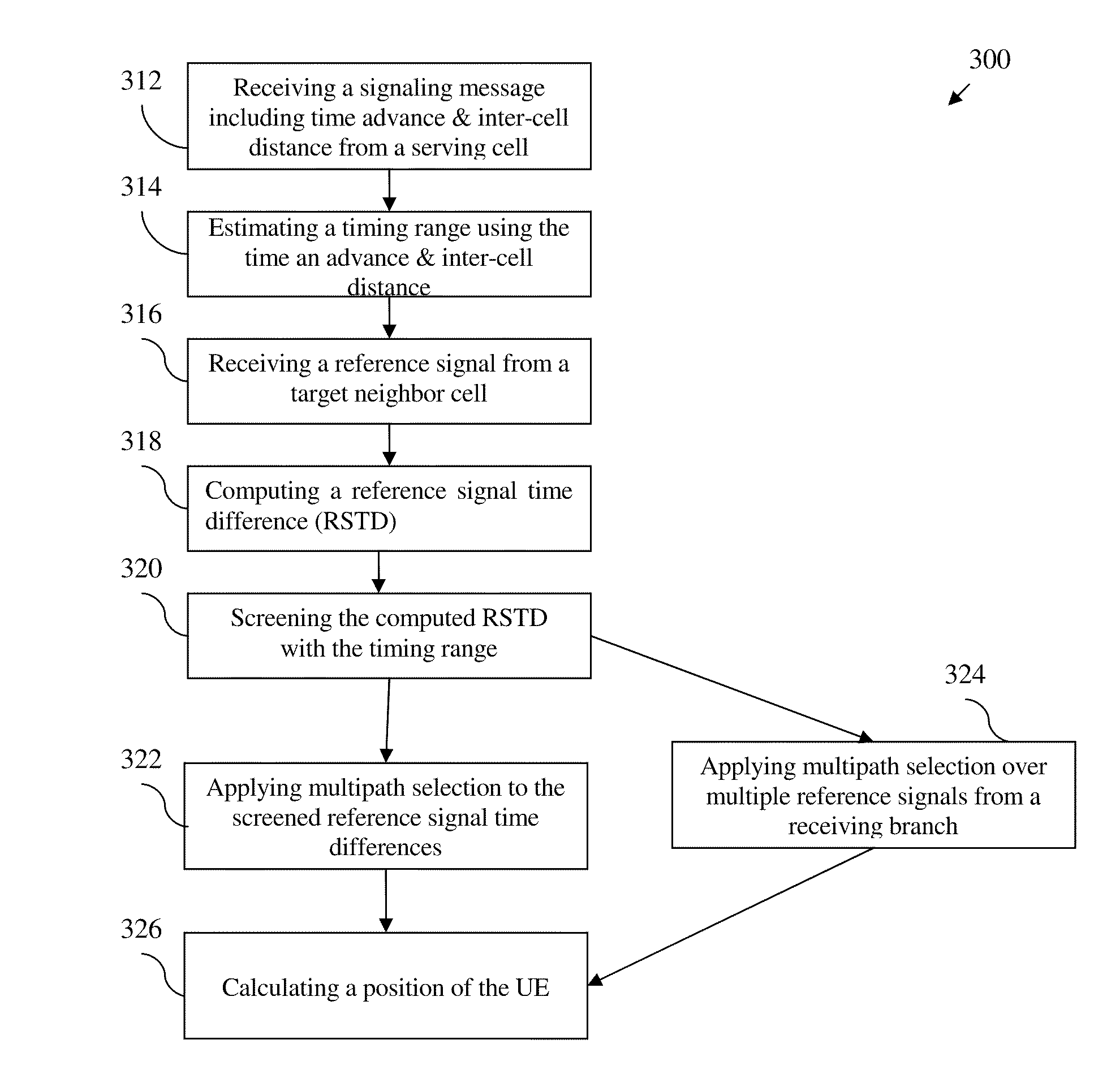
[0015]The disclosure employs a timing advance and an inter-cell distance to proximate a valid timing range and then use the timing range to screen the reference signal time difference (RSTD) values to eliminate those out of range values. This helps narrow down the range of and consequently more accurately position the user equipment.

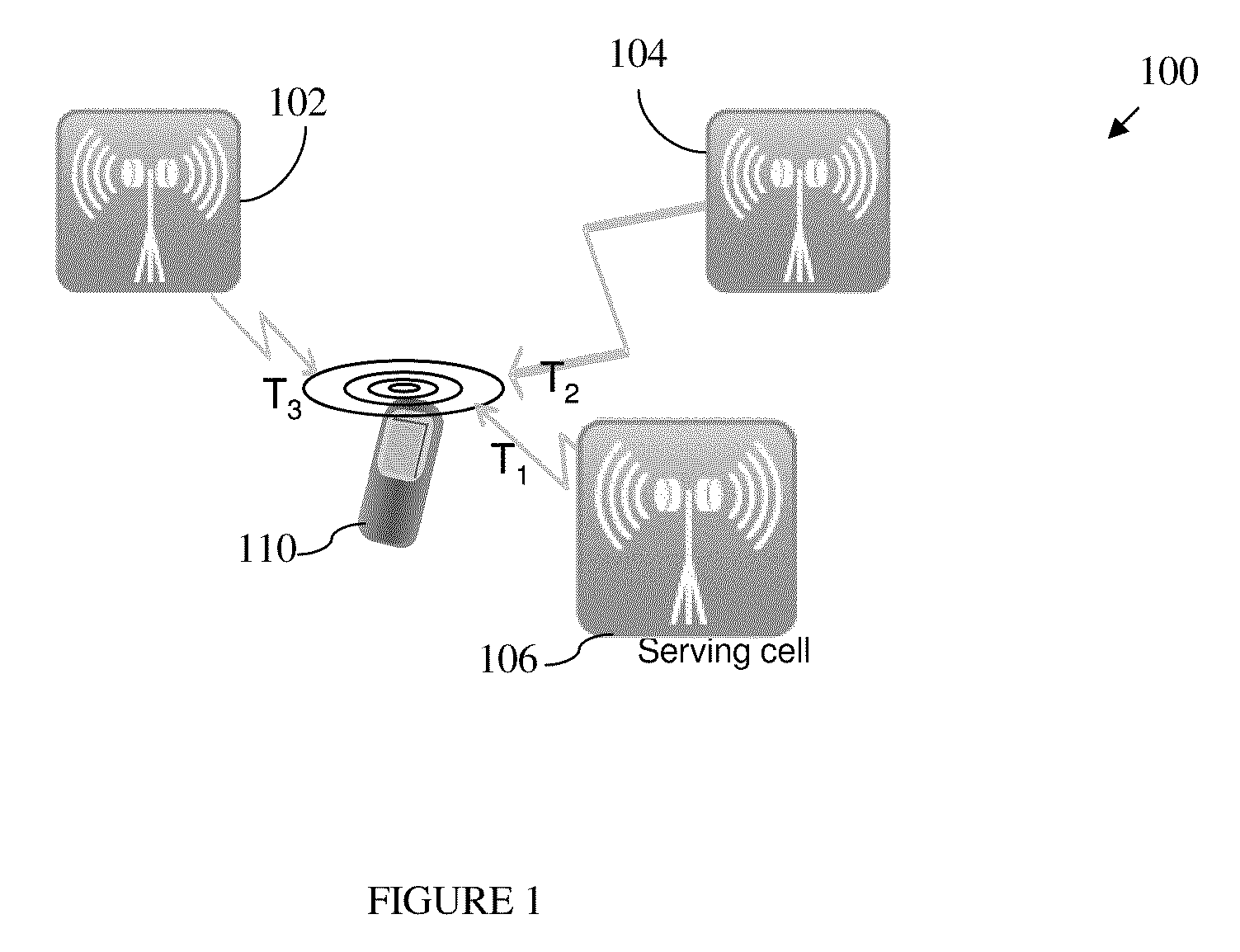
[0016]FIG. 1 illustrates an example wireless network 100. The wireless network 100 includes two neighbor cells 102 and 104, a serving cell 106, and a user equipment 110. The UE 110 is within the range to communicate with at least the serving cell 106 and the two neighbor cells 102 and 104. The two neighbor cells 102 and104 are also called target cells because they are target to be used for calculating the position of the UE 110. There may be other neighbor cells within the reach of the UE and at a minimum two target cells with strongest signals may be selected along with the serving cell to calculate the position of the UE, based on a trilateration algor...


PUM


Abstract

In accordance with an example embodiment of the present invention, a method is disclosed that comprises receiving a reference signal from each of at least two target neighbor cells via at least one receiving branch at a user equipment; estimating a timing range based at least on one of a timing advance for a serving cell and an inter-cell distance between the target neighbor cell and the serving cell; computing a reference signal time difference for the received reference signal from the target neighbor cell; and screening the computed reference signal time difference using the estimated timing range.

Description

TECHNICAL FIELD[0001]The present application relates generally to an apparatus and a method for positioning a wireless user equipment.BACKGROUND[0002]The number of 911 calls made from wireless phones has been increasing steadily. For example, it is estimated that about 50 percent of the millions of emergency 911 (E911) calls in U.S. on daily basis are placed from wireless phones and the percentage is growing. A method for more accurately positioning a user equipment (UE) is needed to meet the US Federal Communications Commission (FCC) E911 requirements of newer generation of wireless. For example, one requirement for Long-Term Evolution (LTE) based wireless E911 calls is that the calling UE be located within 50 meters for 67% of calls and within 150 meters for 95%.[0003]One common method for positioning a UE is based on an observed time difference of arrival (OTDOA). In this approach, a UE reports an observed time difference (OTD) relative to the serving base station such as LTE evo...

Claims


Application Information

Patent Timeline
IPC IPC(8): H04W24/00H04B17/00
CPCG01S5/0215G01S5/14H04B17/27H04W64/00G01S5/0273H04B7/022
Inventor CHARBIT, GILLESKOIVISTO, TOMMI TAPANI
Owner WSOU INVESTMENTS LLC
Why Eureka
Try Eureka