
Pipe End Machining Device with Axial Autofeed

a technology of machining device and pipe end, which is applied in the direction of interengaging clutches, manufacturing tools, portable lathes, etc., can solve the problems of insufficient bevel formation and constant attention of operators in the operation of such machines

Active Publication Date: 2011-02-24
ILLINOIS TOOL WORKS INC
View PDF29 Cites 35 Cited by
  • Summary
  • Abstract
  • Description
  • Claims
  • Application Information

AI Technical Summary

Benefits of technology

[0007]The device further includes a control for controlling the outer limits of movement of the cam follower thereby controlling the rate at which the gearing is rotated thereby controlling the rate of axial movement of the feed screw and axial movement of the cutting tool. Accordingly, adjustment of the control changes the limits of movement of the cam follower and changes the axial speed of the cutting tool, thereby changing the angle of the bevel being cut. By merely changing the control, the device will change the angle of the bevel being cut without requiring an operator to reconfigure the machine.

Problems solved by technology

However, the operation of such a machine requires constant attention from the operator.
It may take forty-five minutes or longer for a machine to cut a bevel at the distal end of a length of pipe, and if the operator fails to properly adjust the feed screw after each revolution or sequence of revolutions of the cutting tool, the bevel will not be properly formed.

Method used


Image

  • Pipe End Machining Device with Axial Autofeed
  • Pipe End Machining Device with Axial Autofeed
  • Pipe End Machining Device with Axial Autofeed

Examples


Embodiment Construction

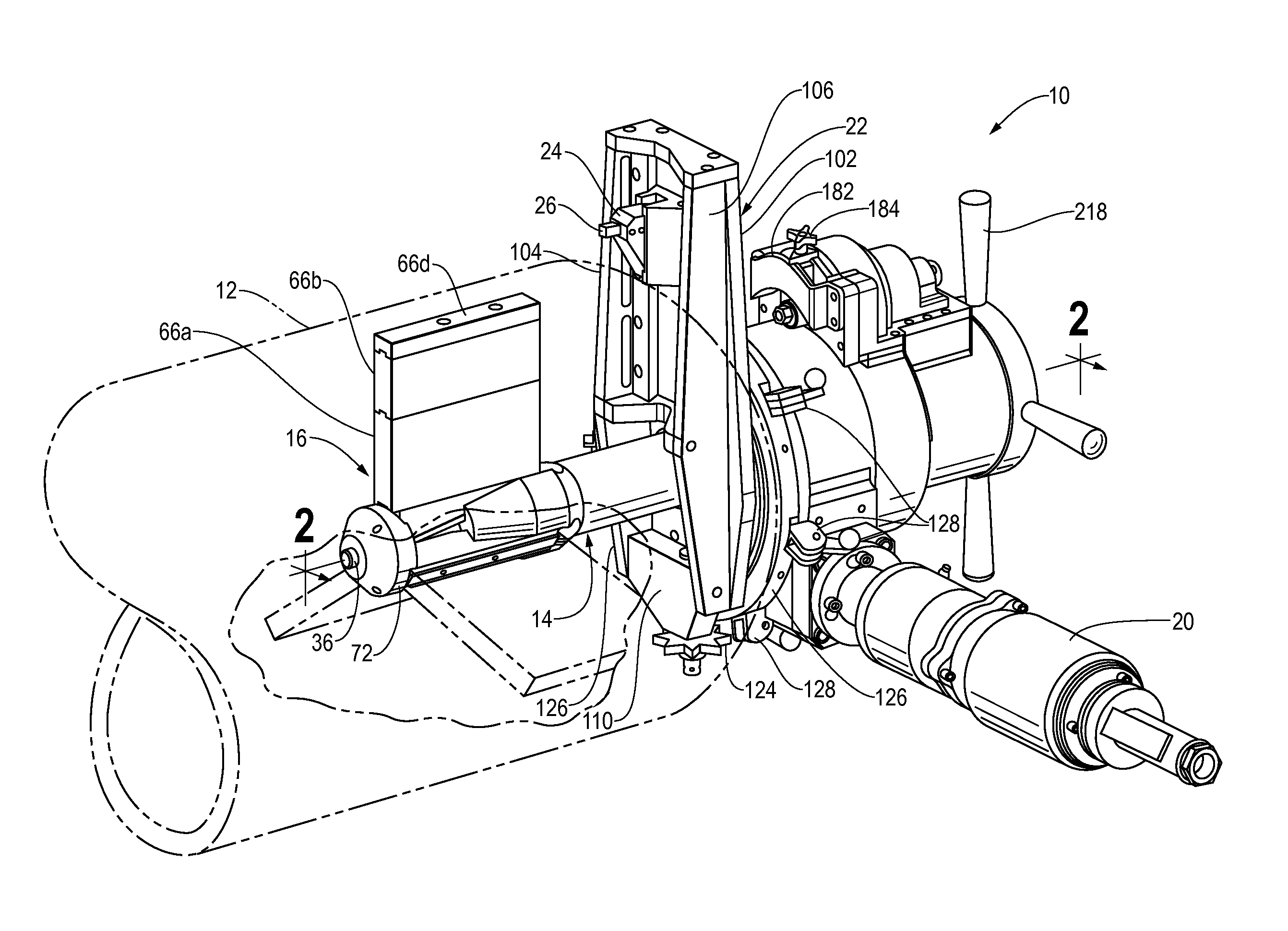
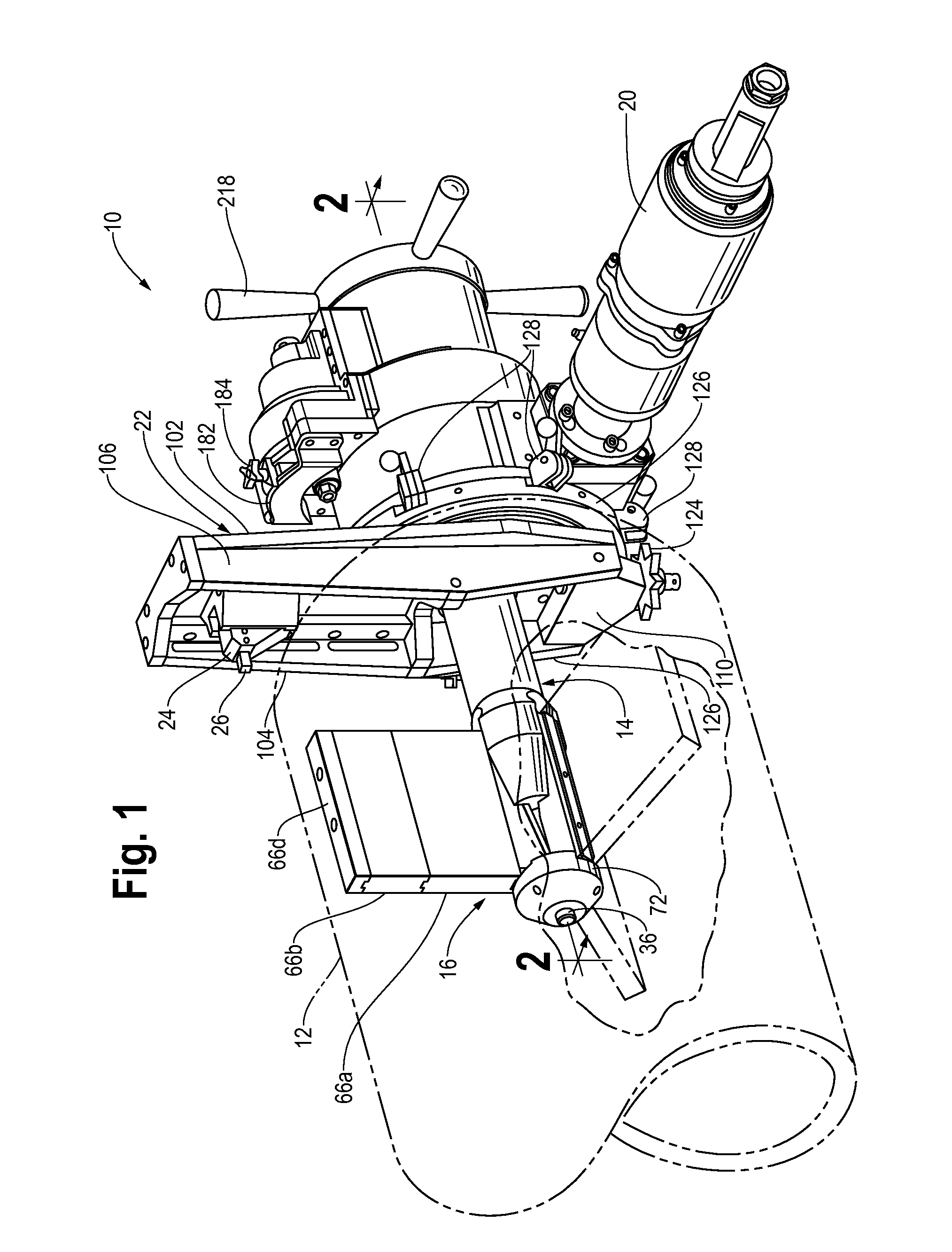
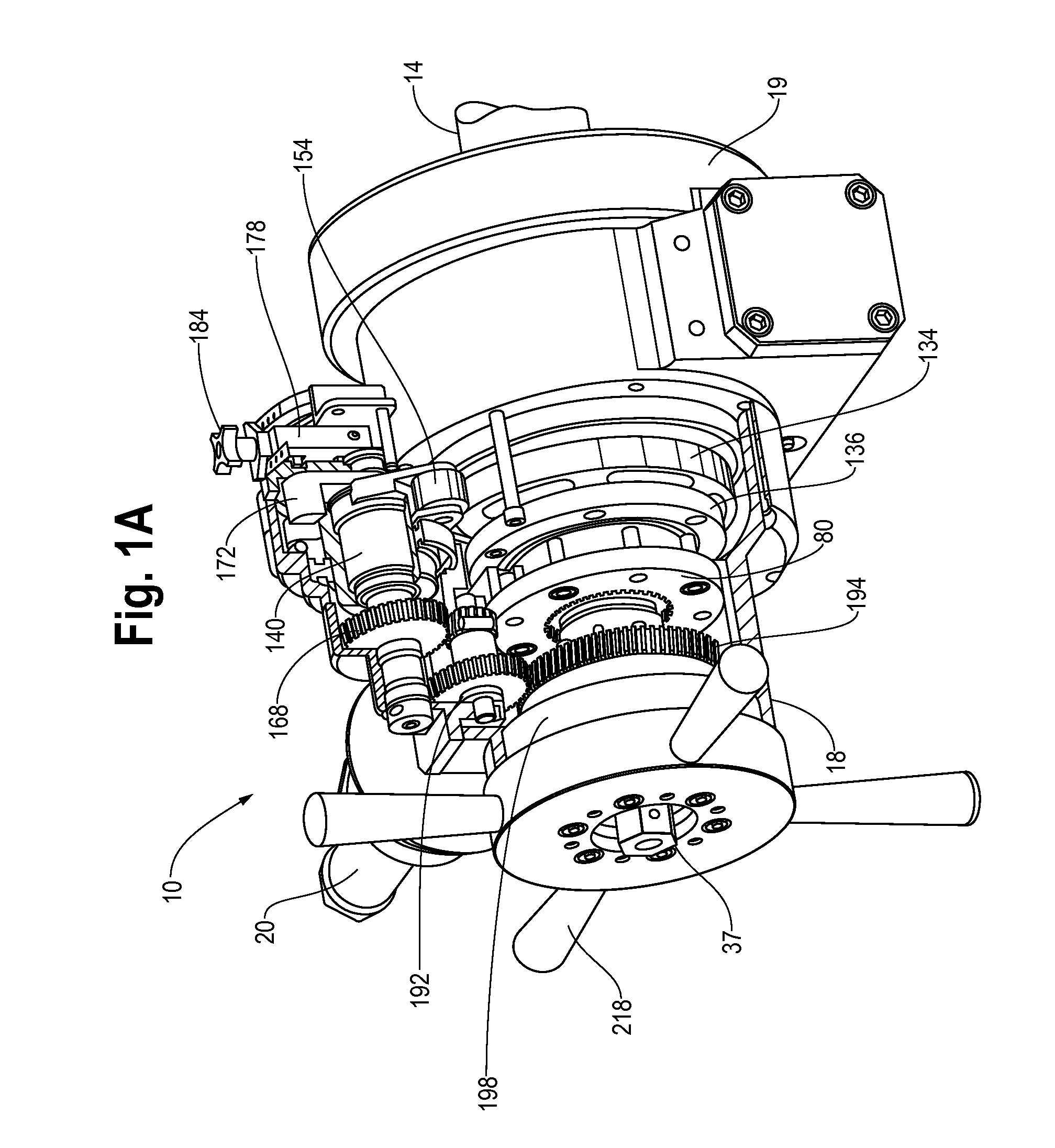
[0040]Referring to FIGS. 1, 2, and 3, a device 10 for machining the distal end of a length of pipe 12 has an elongate central shaft or mandrel 14 at one end of which is a mounting assembly 16 for retaining the mandrel 14 axially aligned with the longitudinal axis of the pipe 12 and at the opposite end of which are housing portions 18 and 19 that assemble together and are non-rotatable with respect to the mandrel 14. The device also includes a motor 20, a rotating arm 22, and radially moveable along the arm 22 a tool holder 24 for retaining a cutting tool 26. When in operation, the arm 22 rotates around the mandrel 14 and the cutting tool 26 is moved by the tool holder 20 and the arm 22 to cut a compound bevel 27 at the outer end of the length of pipe 12.

[0041]To cut a compound bevel 27, the device 10 includes an adjustable autofeed 28 that can adjustably fix the axial rate at which the housing 18, 19 is axially advanced with respect to the mandrel 14 thereby axially moving the arm 2...


PUM

PropertyMeasurementUnit
Lengthaaaaaaaaaa
Angleaaaaaaaaaa
Diameteraaaaaaaaaa

Abstract

A device for preparing the end of a pipe includes a non-rotatable mandrel one end of which is attachable to the pipe. A motor rotates a sleeve around the mandrel and the sleeve retains an arm perpendicular to the mandrel for cutting the pipe. A cam surface on the rotating sleeve moves a cam follower. Movement of the cam follower is converted to rotational movement for turning a feed nut threaded on the mandrel. The rate at which the sleeve is advanced by the feed nut is controlled by limiting the movement of the cam follower.

Description

[0001]The applicants claims priority from their previously filed provisional application assigned Ser. No. 61 / 235,768 and filed Aug. 21, 2009. The present invention relates to a device for machining the end of a pipe to provide a bevel suitable for welding and in particular to an autodrive for machining a compound bevel angle without requiring the reconfiguration of the machine.BACKGROUND OF THE INVENTION[0002]Extended piping requires that shorter lengths of pipe be welded together end to end to form a longer section and prior to joining two lengths together, the mated ends must be machined to receive a weld. Where the wall of the pipe is relatively thin, the distal end of the pipe may be machined into a simple bevel. Where the wall of the pipe is thicker, a compound bevel is required. A typical compound bevel has one portion angled at ten degrees and a second portion angled at thirty-seven degrees.[0003]Machines that bevel the distal end of a length of pipe are elongate with a firs...

Claims


Application Information

Patent Timeline
IPC IPC(8): B23B5/16F16D11/06
CPCB23B5/162Y10T82/22B23B2260/004B23B5/168B23B2260/104
Inventor WEINBERG, JEREMY E.WOZNIAK, MARK
Owner ILLINOIS TOOL WORKS INC
Learn More