
Micro electromechanical system connector and method for manufacturing same

a technology of micro electromechanical system and connector, which is applied in the direction of microstructural device, coupling device connection, microstructural technology, etc., can solve the problem of difficulty in manufacturing small connectors with electrode gaps less than 0.3 millimeters

Inactive Publication Date: 2011-02-24
HON HAI PRECISION IND CO LTD
View PDF8 Cites 4 Cited by
  • Summary
  • Abstract
  • Description
  • Claims
  • Application Information

AI Technical Summary

Benefits of technology

The present patent relates to micro electromechanical system (MEMS) connectors and a method of manufacturing the same. The technical effect of the patent is to provide a new method for manufacturing small connectors that can overcome the limitations of current methods, such as difficulty in manufacturing connectors with electrode gaps less than 0.3 millimeters. The new method allows for the manufacturing of MEMS connectors with electrode gaps as small as 0.15 millimeters.

Problems solved by technology

However, in a typical method of manufacturing connectors, such as a module punching, it is difficult to manufacture small connectors having electrode gaps less than 0.3 millimeters.

Method used


Image

  • Micro electromechanical system connector and method for manufacturing same
  • Micro electromechanical system connector and method for manufacturing same
  • Micro electromechanical system connector and method for manufacturing same

Examples


Embodiment Construction

[0014]Reference will now be made to the drawings to describe various inventive embodiments of the present disclosure in detail, wherein like numerals refer to like elements throughout.

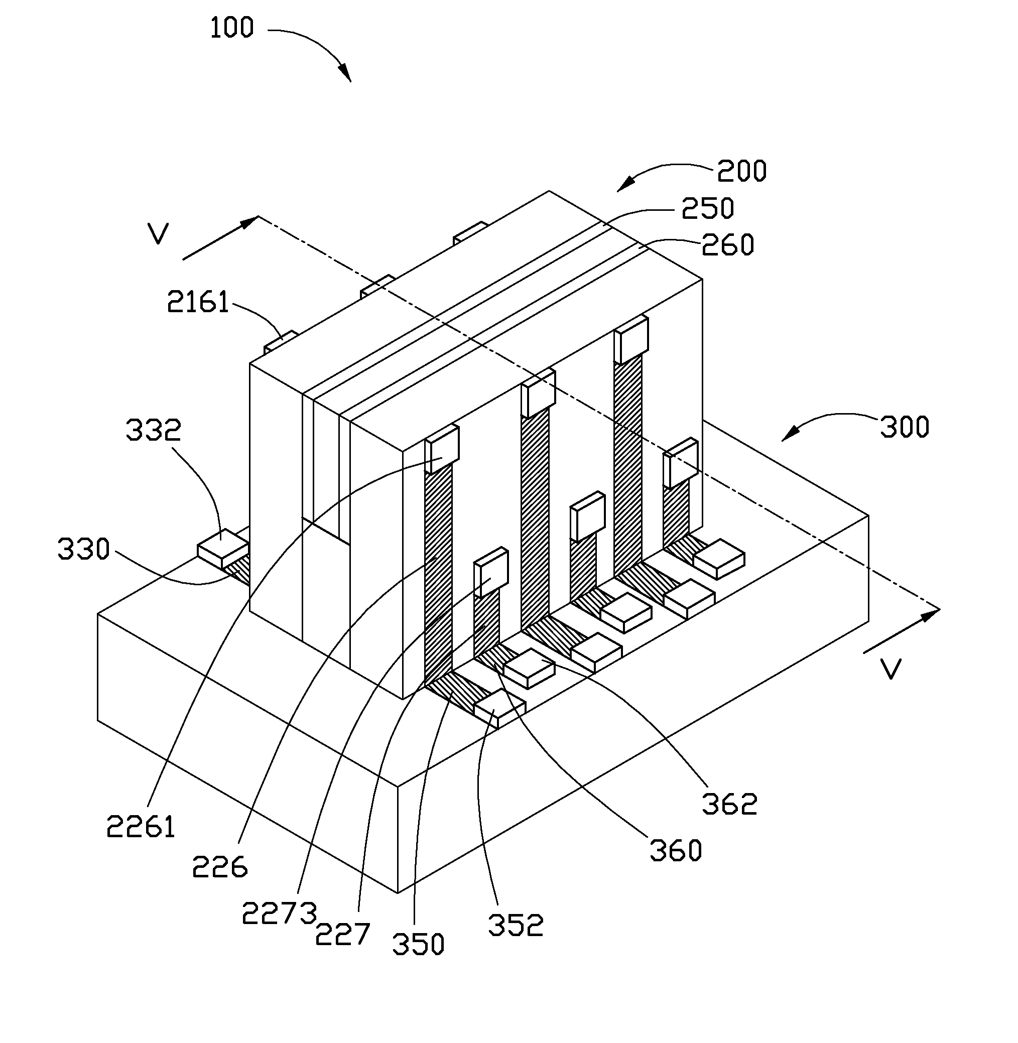
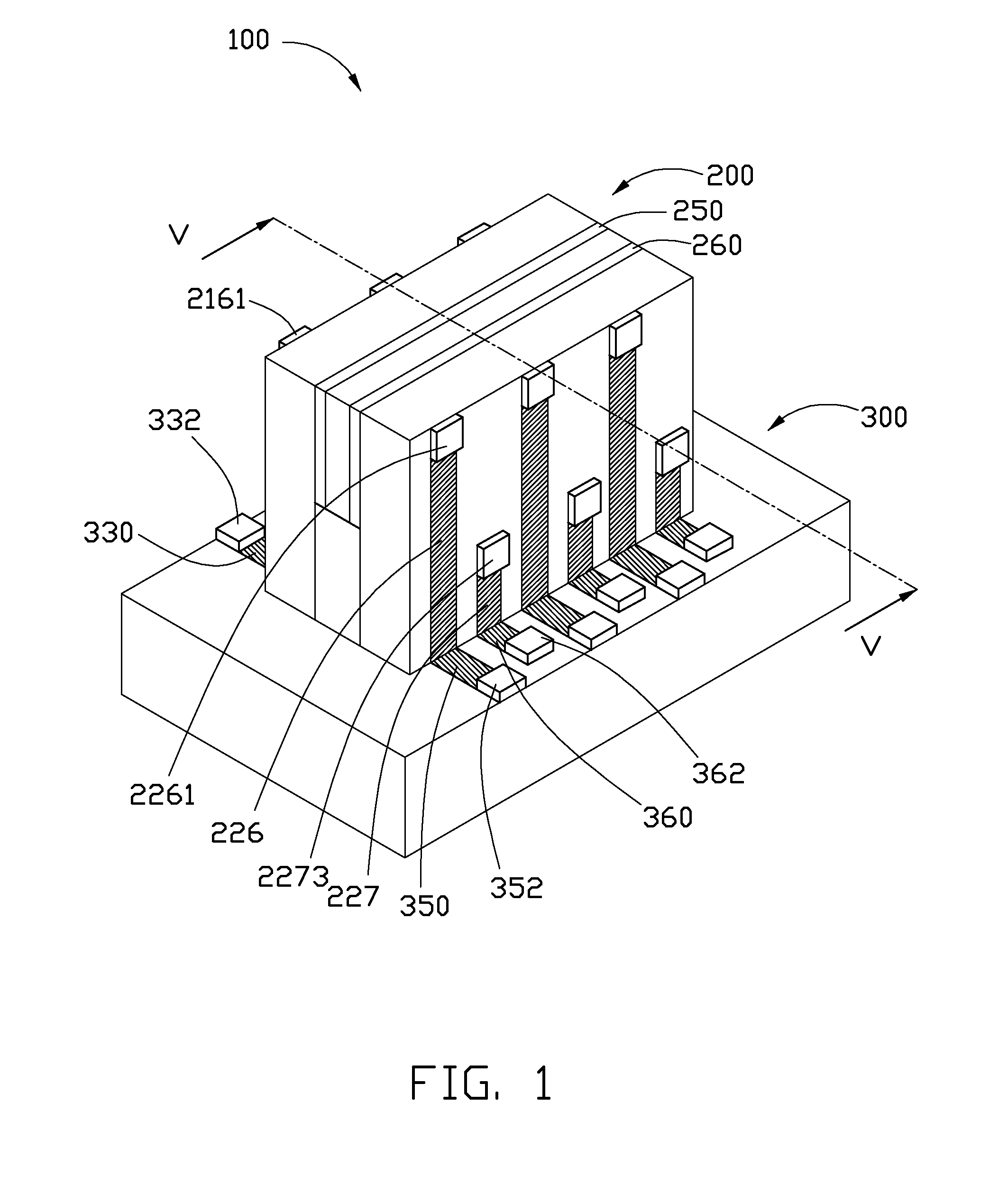
[0015]Referring FIGS. 1 to 5, a micro electromechanical system (MEMS) connecter assembly 100 according to one embodiment of the present disclosure is shown. The MEMS connecter assembly 100 includes a MEMS plug connecter 200 and a MEMS socket connecter 300. The MEMS plug connecter 200 and the socket connecter 300 can be mounted on an external circuit board by wire bonding method or surface mounting technology.

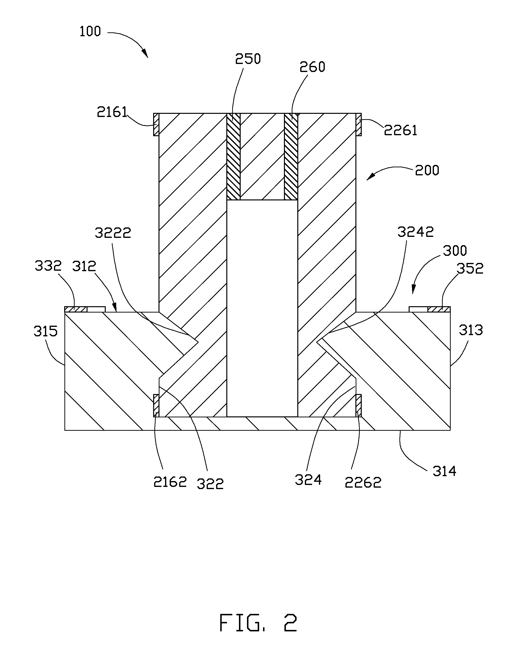
[0016]Referring to FIGS. 3 to 4, the MEMS plug connecter 200 includes a first square substrate 210, a second square substrate 220 facing the first substrate 210, a spacing slat 230, a first insulating layer 250, and a second insulating layer 260.

[0017]The first substrate 210 includes a first surface 211, a second surface 212 opposite to the first surface 211, a first side wall 213, and a second sid...


PUM

PropertyMeasurementUnit
electrically conductiveaaaaaaaaaa
conductiveaaaaaaaaaa
widthaaaaaaaaaa

Abstract

A micro electromechanical system connecter includes a u-shaped plug connecter and a socket connector. The plug connecter includes two opposite substrates and a spacing element sandwiched therebetween and positioned at one ends of the two substrates. Two parallel grooves are defined in outer surfaces of the two substrates at the other ends the two substrates. A plurality of parallel first electrodes formed on the outer surfaces of the two substrates and configured to extend along a direction perpendicular to grooves. The socked connecter includes a base having a top surface. A recess is defined in the top surface. Two protrusions are respectively formed on two internal walls of the recess adjacent to the entrance of the recess. A plurality of parallel second electrodes formed on the base according to the first electrodes. Each second electrode extends from the top surface of the base to one of the two internal walls of the recess.

Description

BACKGROUND[0001]1. Technical Field[0002]The present disclosure relates micro electromechanical system (MEMS) connectors and a method for manufacturing the MEMS connectors.[0003]2. Description of Related Art[0004]As electrical devices such as personal digital assistants (PDAs) and notebook computers become smaller, the need for ever smaller connectors grows. However, in a typical method of manufacturing connectors, such as a module punching, it is difficult to manufacture small connectors having electrode gaps less than 0.3 millimeters.[0005]Therefore, a new connector and a method for manufacturing the same are desired to overcome the above-described shortcoming.BRIEF DESCRIPTION OF THE DRAWINGS[0006]The components in the drawings are not necessarily drawn to scale, the emphasis instead being placed upon clearly illustrating the principles of at least one embodiment. In the drawings, like reference numerals designate corresponding parts throughout the various views.[0007]FIG. 1 is a ...

Claims


Application Information

Patent Timeline
Patent Type & Authority Applications(United States)
IPC IPC(8): H01R12/02H01R43/02
CPCB81B7/0006H01R43/205H01R12/721H01R2107/00Y10T29/4921H01L2924/0002H01R24/60H01L2924/00
Inventor CHANG, JEN-TSORNG
Owner HON HAI PRECISION IND CO LTD
Learn More