
Connector

a technology of connecting rods and connectors, applied in the direction of couplings/cases, coupling device connections, securing/insulating coupling contact members, etc., can solve the problems of difficult molding small connectors, complicated structure of molds for forming guiding grooves and lock receiving portions, etc., to achieve less complex molds, small connectors, and simplified housings

Active Publication Date: 2016-08-02
SUMITOMO WIRING SYST LTD
View PDF13 Cites 5 Cited by
  • Summary
  • Abstract
  • Description
  • Claims
  • Application Information

AI Technical Summary

Benefits of technology

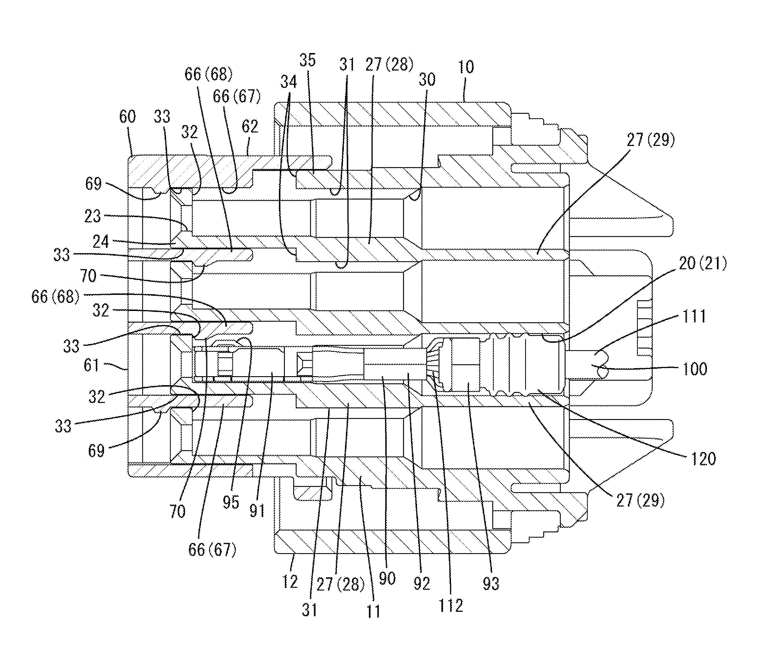
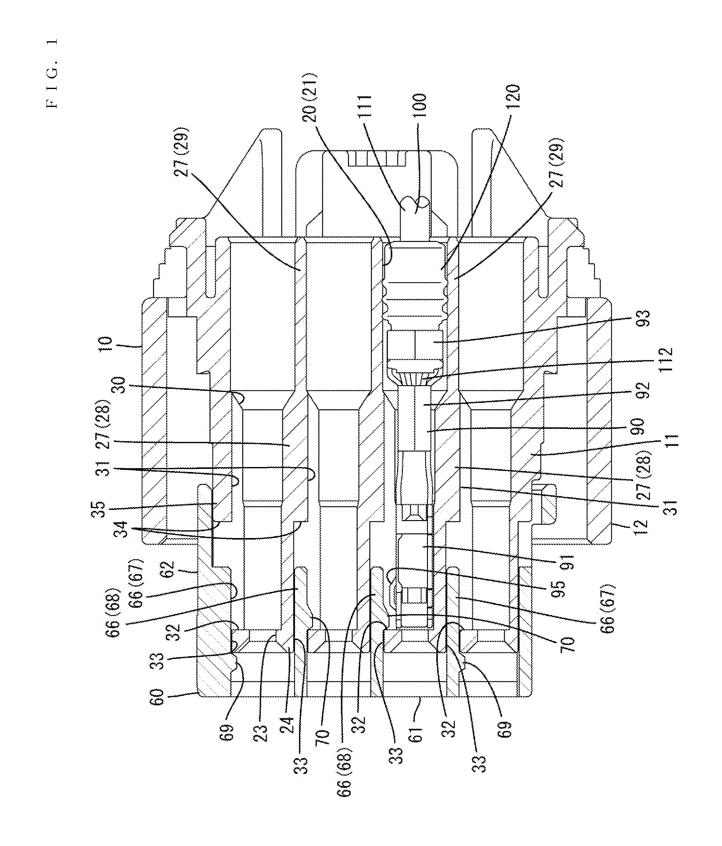
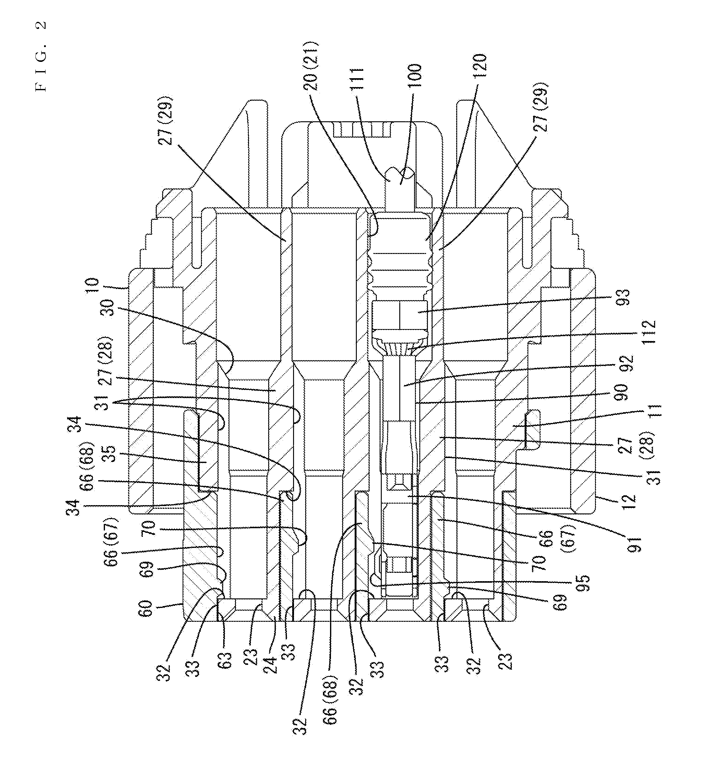
The patent describes a housing structure that simplifies the process of inserting terminal fittings and locking a retainer. The housing has guiding grooves and closed front ends that engage the locks of the retainer to prevent it from coming out. This means that the housing does not need a separate structure for guiding the terminal fittings and locking the retainer, which makes the housing more compact and allows for smaller connectors. The housing has a rubber plug that is inserted into the terminal fitting and a larger diameter cavity to hold the rubber plug securely. The guiding groove is positioned in a way that allows for a smaller housing size and prevents the width of the housing from increasing due to the guiding grooves.

Problems solved by technology

Thus, the structure of a mold for forming the guiding grooves and the lock receiving portions may become complicated and there is difficulty molding small connectors.

Method used


Image

  • Connector
  • Connector
  • Connector

Examples


Embodiment Construction

[0018]An embodiment of the invention is described with reference to FIGS. 1 to 6. A connector of this embodiment includes a housing 10 made of synthetic resin, a retainer 60 made of synthetic resin and terminal fittings 90 made of electrically conductive metal. The housing 10 is connectable to an unillustrated mating housing. In the following description, an end where the mating housing is located with respect to the housing 10 at the start of connection is referred to as a front end concerning a front-back direction and a vertical direction is based on FIGS. 3 to 5. Further, a width direction is synonymous with a lateral direction of FIG. 5 in the following description.

[0019]As shown in FIGS. 5 and 6, the housing 10 includes a housing main body 11 in the form of a flat block in the width direction, a tubular fitting tube 12 surrounds the housing main body 11 and a radially extending coupling 13 connects the fitting tube 12 and the housing main body 11. A connection space 14 is open...


PUM


Abstract

In the process of inserting a terminal fitting (90) into a cavity (20) of a housing (10), a stabilizer (95) enters a guiding groove (31) and an inserting operation of the terminal fitting (90) is guided. The front end of the guiding groove (31) defines a closed end part (32). When a retainer (60) is mounted into the housing (10), locking portions (66) are inserted into communication holes (33) and locked to the closed end parts (32) of the guiding grooves (31), thereby preventing the retainer (60) from coming out of the housing (10).

Description

BACKGROUND[0001]1. Field of the Invention[0002]The present invention relates to a connector.[0003]2. Description of the Related Art[0004]Japanese Unexamined Patent Publication No. 2013-218902 discloses a connector that has a housing with cavities, terminal fittings to be inserted into the respective cavities from behind and a retainer to be mounted into the housing from the front. A deflectable locking lance is provided at an inner wall of the cavity of the housing and a deflection space for the locking lance is open on the front surface of the housing. A guiding groove is provided on the inner surface of the lower wall of each cavity and extends in a front-back direction. Further, a forwardly open entrance groove is provided on a partition wall between the cavities and extends in the front-back direction of the housing. A lock receiving portion is provided at a position facing the entrance groove.[0005]The terminal fitting includes a stabilizer projecting downwardly from the lower ...

Claims


Application Information

Patent Timeline
Patent Type & Authority Patents(United States)
IPC IPC(8): H01R13/40H01R13/436H01R13/432H01R13/52
CPCH01R13/432H01R13/4364H01R13/5208
Inventor HASHIMOTO, NORIHITO
Owner SUMITOMO WIRING SYST LTD
Learn More