Illumination System For Variable Direction Of View Instruments

an illumination system and variable direction technology, applied in the field of illumination systems for viewing instruments, can solve the problems of affecting the illumination effect of the instrument, and achieving the effect of reducing the illumination

Active Publication Date: 2011-02-24
KARL STORZ IMAGING INC
View PDF52 Cites 7 Cited by
  • Summary
  • Abstract
  • Description
  • Claims
  • Application Information

AI Technical Summary

Benefits of technology

[0015]It is a further object of the present invention to provide an illumination system for a scope that can provide illumination in a generally circular band around the pivot axis of the view vector of the scope.
[0016]It is yet another object of the present invention to provide an illumination system for a scope that can provide illumination that covers the entire viewing range of the viewing field as the view vector pivots around the view vector.
[0017]It is still another object of the present invention to provide an illumination system for a scope that will freely rotate with the scope.

Problems solved by technology

Although such fiber optic systems tend to suffer from a number of disadvantages, including some light loss during the transmission from the external source to the tip of the scope, gradual discoloration and loss of transmission efficiency over time, and the breaking of fiber strands, these systems continue to be the most commonly employed method of providing illumination to the viewing site.
However, while this type of arrangement can accommodate a large viewing range, it cannot be made sufficiently compact for midsize (i.e., 4 mm diameter) to small (1 mm diameter) endoscopes.
However, while these arrangements can be made relatively compact, they can only illuminate a limited swing range.
An additional challenge presented by variable direction of view scopes is that, in addition to changing the viewing elevation, it also desirable to be able to rotate the line of sight azimuthally about the shaft of the endoscope in order to achieve truly complete variable viewing.
However, this has the disadvantage that the light guide gets wrapped around the instrument in the process.
Likewise, endoscopes, that have a fixed handle and a rotatable shaft, allowing the user to perform an azimuthal scan without having to rotate the entire instrument, have a similar problem.
However, in practice, these systems have not proven sufficiently effective to replace the standard solution, which entails leaving slack in the fiber bundle in order to give it some freedom to twist.
This limited rotation restricts viewing freedom by forcing the operator to reset the viewing direction once the end of a particular range has been reached.

Method used


Image

  • Illumination System For Variable Direction Of View Instruments
  • Illumination System For Variable Direction Of View Instruments
  • Illumination System For Variable Direction Of View Instruments

Examples


Embodiment Construction

[0034]The basic system of one embodiment for providing illumination for an endoscope having a variable direction of view and in accordance with the invention are illustrated in FIGS. 2-6. As used in the description and drawings, any terms or illustrations referencing the orientation or movement of parts of the system, such as references to “top,”“bottom,”“above,”“below,”“over,”“under,”“above,”“beneath,”“on top,”“underneath,”“up,”“down,”“upper,”“lower,”“front,”“rear,”“back,”“forward” and “backward”, refer to the objects referenced when in the orientation illustrated in the drawings, which orientation is not necessary for achieving the objects of the invention.

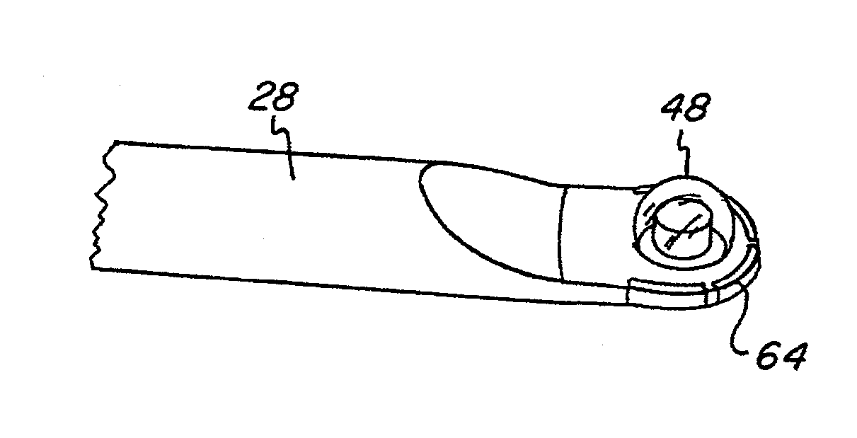
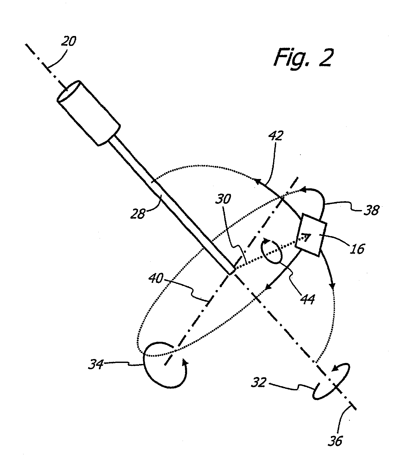
[0035]FIG. 2 illustrates the basic operating principles of a variable direction of view endoscope used in accordance with the invention. Such an instrument generally includes a shaft 28 with a longitudinal axis 36. The endoscope has a view vector 30, with an attendant view field 16, with at least two degrees of freedom 32, 34. T...


PUM


Abstract

An illumination system for variable direction of view instruments is disclosed generally comprising an endoscope having a longitudinal axis and a variable view vector that pivots about a pivot axis angularly offset from the longitudinal axis. The view vector has an attendant viewing field that travels along a path as the view vector pivots, defining a viewing range. A source of illumination is arranged in a plane offset from the plane in which the view vector pivots and provides an annular, solid angle of illumination that covers the viewing range. In certain embodiments, the pivot axis is perpendicular to the longitudinal axis and the illumination plane is parallel to the pivot plane. In some embodiments, the source of illumination is a plurality of light emitting diodes arranged around the pivot axis.

Description

CROSS-REFERENCE TO RELATED APPLICATIONS[0001]This application is a continuation application of pending U.S. patent application Ser. No. 11 / 339,201 for an “Illumination System For Variable Direction View Instruments”, filed on Jan. 25, 2006, which claims the benefit of, under Title 35, United States Code, Section 119(e), U.S. Provisional Patent Application No. 60 / 647,359, filed Jan. 26, 2005, the contents of each of which are incorporated by reference herein in their entirety.FIELD OF THE INVENTION[0002]The present invention relates to a system for an illumination system for viewing instruments, such as endoscopes. More specifically, the invention relates to a system for illuminating the viewing field in a scope with a variable direction of view.BACKGROUND OF THE INVENTION[0003]Illumination systems for viewing instruments, such as endoscopes, industrial boroscopes, or other types of scopes, are generally well known in the art. Because the sites being viewed or inspected by such scope...

Claims


Application Information

Patent Timeline
Patent Type & Authority Applications(United States)
IPC IPC(8): A61B1/06F21V21/00F21S4/00
CPCA61B1/00177A61B1/00183A61B1/0607A61B1/00032A61B1/0623A61B1/0676A61B1/0684A61B1/0615
Inventor HOEG, HANS DAVIDHALE, ERIC L.SCHARA, NATHAN JONTESAR, JOHN C.
Owner KARL STORZ IMAGING INC
Why Eureka
Try Eureka