
Viewing instrument

a technology of viewing instruments and mouthpieces, applied in the field of dental instruments, can solve the problems of extremely restricted space for two people (three hands) around the limited area of the mouth of a patien

Inactive Publication Date: 2005-12-15
COLETON STUART
View PDF3 Cites 13 Cited by
  • Summary
  • Abstract
  • Description
  • Claims
  • Application Information

AI Technical Summary

Problems solved by technology

Quite apart from the inconvenience of having a third party hold a mirror at the precise angle at which the dentist obtains the best view of the area under inspection, the space for two people (three hands) is extremely restricted around the limited area of the mouth of a patient.

Method used


Image

  • Viewing instrument
  • Viewing instrument
  • Viewing instrument

Examples


Embodiment Construction

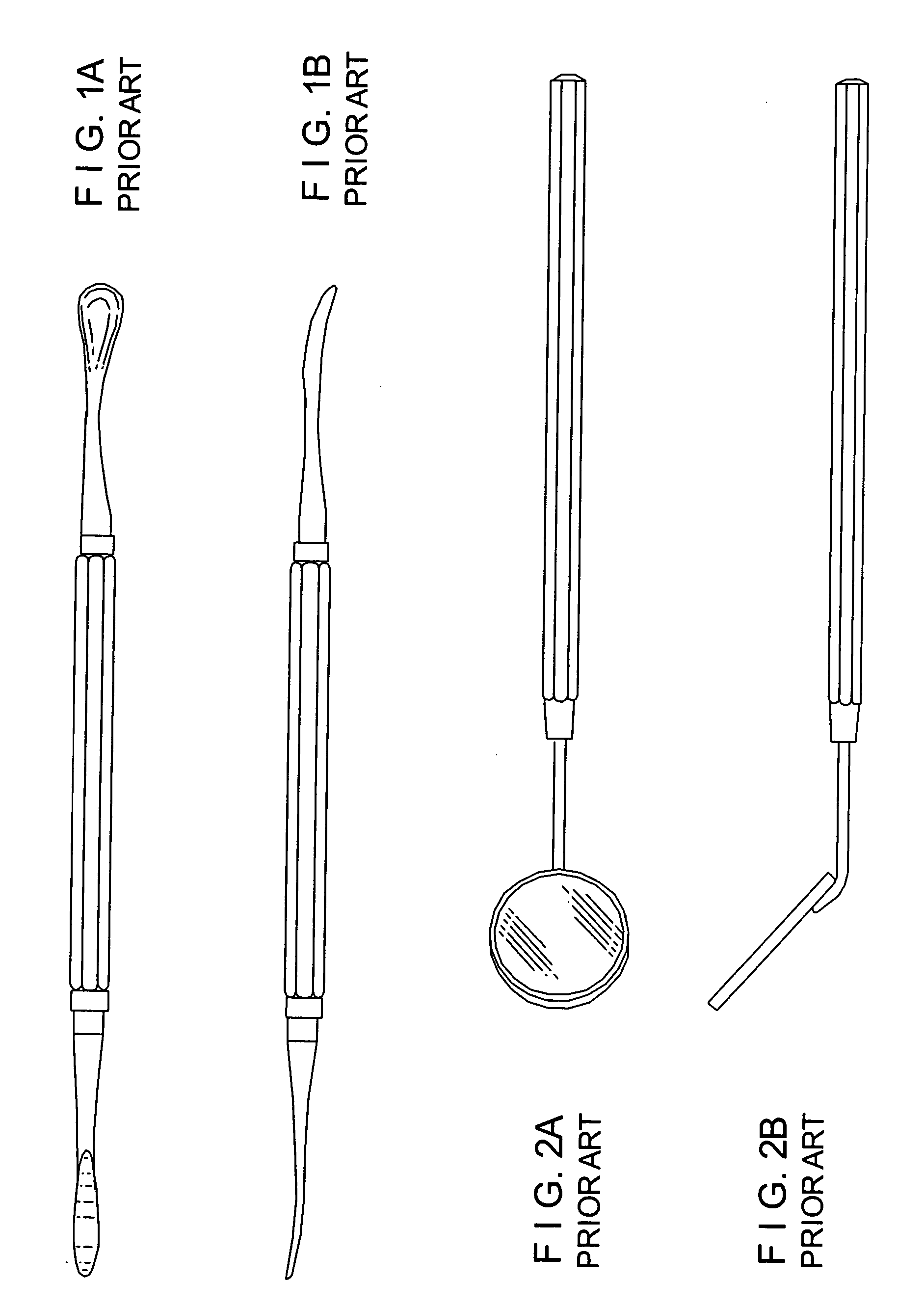
[0036] Referring now to the drawings, FIGS. 1A and 1B show a multipurpose dental instrument in which an elevator 1 and retractor 2 are respectively located at opposite ends of an elongated central handle 3. The implement is a one-piece casting and is discarded if either the elevator 1 or retractor 2 become worn or damaged. In the embodiment shown in FIGS. 1A and 1B, the handle 3 is octagonal in cross section to provide longitudinal flats which facilitate in gripping of the implement. Alternatively, the handle 3 could be knurled, dimpled, or otherwise contoured to facilitate gripping.

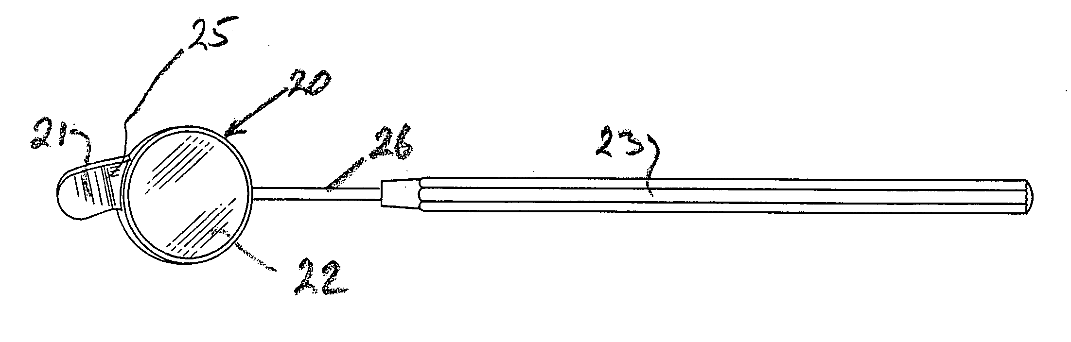
[0037]FIGS. 2A and 2B show a conventional dental mirror having a handle 8 and mirror element 9 at one end thereof. The mirror element 9 is formed by a circular dished receptacle 10 in which a mirror 11 is seated. Although the mirror element can be adhesively secured in the dished receptacle 10, it is preferred that the extremity of the rim of the upstanding walls of the dished receptacle be peened over ...


PUM


Abstract

A viewing instrument, particularly for use in dentistry, in which a finger or like element is attachable to or integral with a mirror to hold material out of the sight-line when viewing the mirror. In the case of a dental implement, the element is a retractor attached or attachable to a dentists inspection mirror.

Description

FIELD OF THE INVENTION [0001] The invention finds particular use in the field of dentistry and will primarily be described in terms of a dental instrument. BACKGROUND OF THE INVENTION [0002] Dentists, dental surgeons, and periodontists traditionally use small viewing mirrors during oral inspections and procedures. Such viewing mirrors can be used on their own during routine dental procedures such as, for example, drilling. However, for a thorough investigation it is usually necessary to observe a portion of a tooth or bone which lies below the gum line and, in order to do this, the gum and / or surrounding tissue must be moved aside to expose the area for inspection. To move gum or tissue aside, a variety of dental instruments may be used, but, most commonly, the instrument used is a dental elevator. An elevator is an elongated instrument having a “pusher” at one end. It is a relatively simple matter for the dentist to hold the mirror in one hand and to orient the reflecting mirror su...

Claims


Application Information

Patent Timeline
Patent Type & Authority Applications(United States)
IPC IPC(8): A61B1/247A61C1/00
CPCA61B1/247
Inventor COLETON, STUART
Owner COLETON STUART
Learn More