Device for observing the inside of a hot cell, hot cell provided with said device, and method for maintaining said device

a technology for observing the inside and outside of the hot cell, which is applied in the field of instruments for hot cells and hot cells fitted, can solve the problems of limiting the capacity to take action in the cell, affecting operations, and difficult to perform manipulations and adjustments, so as to facilitate utilization and maintenance, reduce manufacturing costs, and facilitate operation.

Active Publication Date: 2012-05-10
COMMISSARIAT A LENERGIE ATOMIQUE ET AUX ENERGIES ALTERNATIVES
View PDF15 Cites 12 Cited by
  • Summary
  • Abstract
  • Description
  • Claims
  • Application Information

AI Technical Summary

Benefits of technology

[0044]The invention makes it possible to obtain an observation instrument for a hot cell that is of low manufacturing cost, of lifetime that is increased, and of utilization and maintenance that are facilitated.
[0045]The invention makes it possible in particular to obtain a simple device for viewing in color that is capable of operating under irradiation.

Problems solved by technology

Nevertheless, such manipulations and adjustments may be difficult to perform and they occupy a remote manipulator arm, thereby limiting capacity for taking action in the cell.
Another drawback may result in the presence of a cable inside the cell connecting the sensor to an appliance located outside the cell.
The cable may hinder operations that are to be performed inside the cell and it may be damaged, thereby interrupting operation of the sensor.
Nevertheless, such a window is expensive and it does not enable high quality images to be obtained of all of the zones inside the cell.
A drawback of those instruments is that the observable field is limited; a limited angle of vision means there are some zones within the cell that cannot be observed.
A drawback of instruments that include a dome is that the dome is expensive.
Replacing such a dome runs risks of contamination and radiation, is complex to perform, and takes the hot cell out of action for a long time.
Another drawback of such instruments is that they enable visual observation only; in particular such instruments do not enable length dimensions to be measured between two points within the hot cell.

Method used


Image

  • Device for observing the inside of a hot cell, hot cell provided with said device, and method for maintaining said device
  • Device for observing the inside of a hot cell, hot cell provided with said device, and method for maintaining said device
  • Device for observing the inside of a hot cell, hot cell provided with said device, and method for maintaining said device

Examples


Embodiment Construction

[0053]Unless indicated explicitly or implicitly to the contrary, any elements or members that are structurally or functionally identical or similar are designated in the various figures by references that are identical.

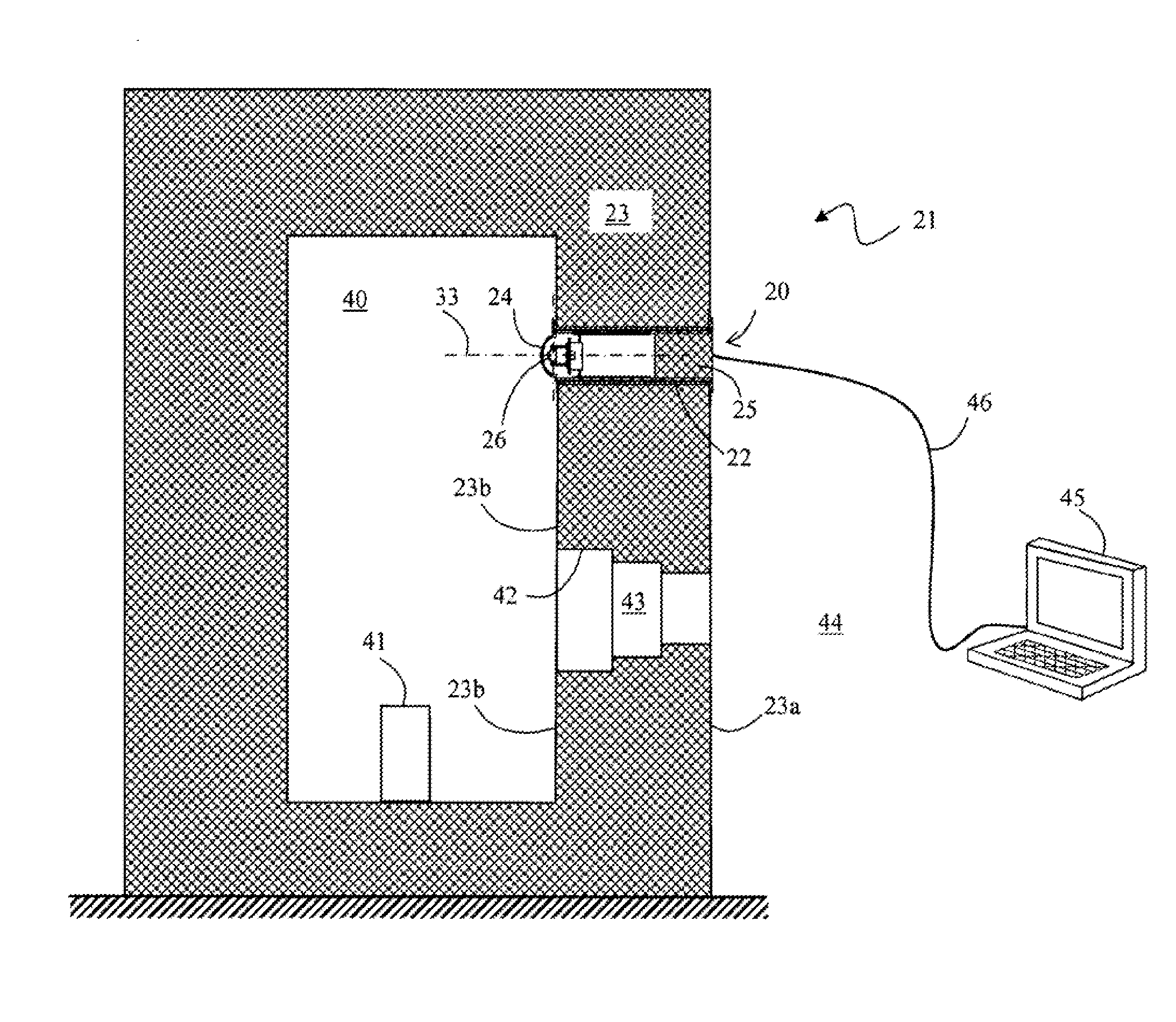
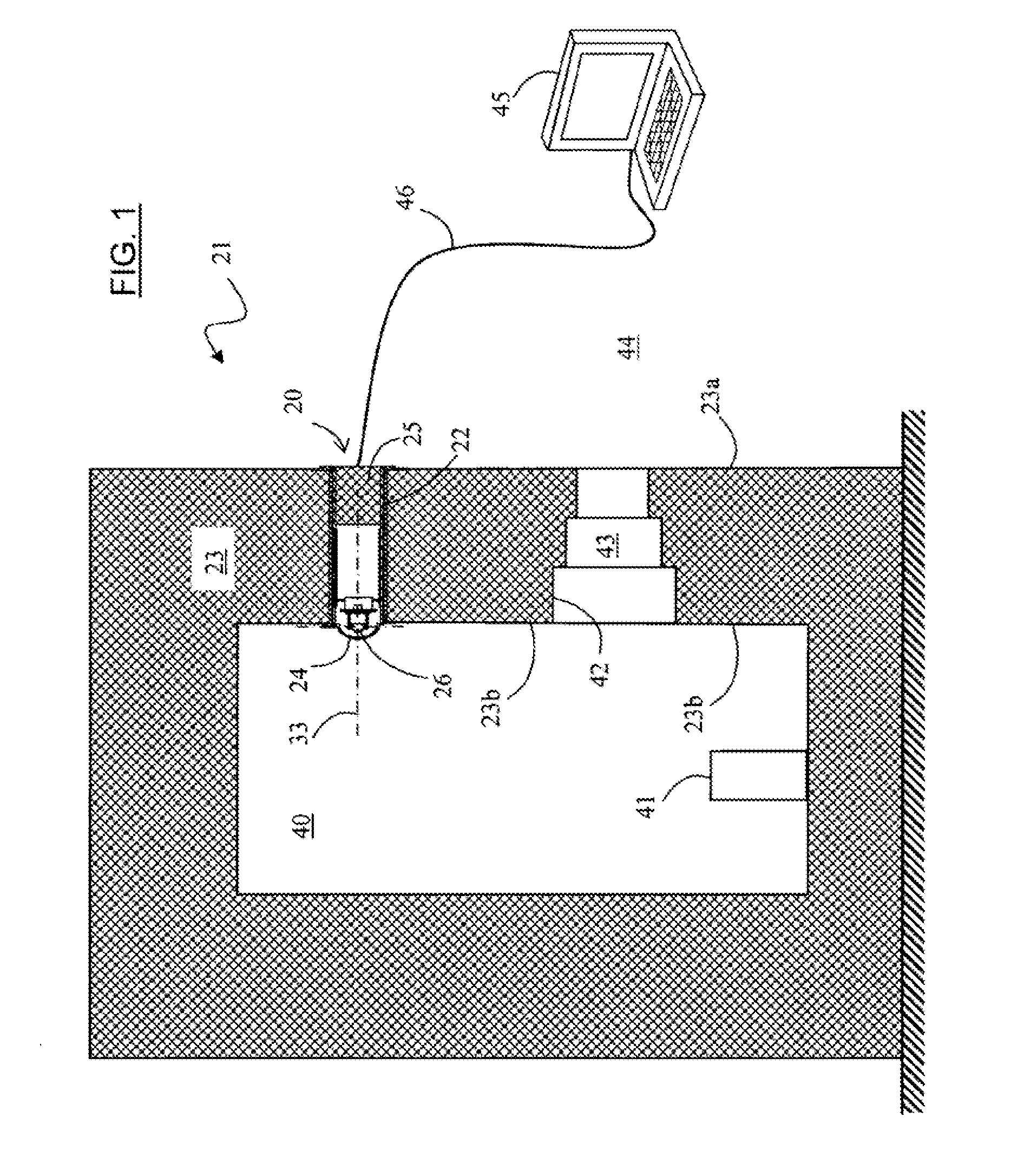
[0054]With reference to FIG. 1 in particular, the hot cell 21 has thick walls 23 defining a chamber 40 in which radioactive items 41 are placed.

[0055]The chamber 40 may be maintained at a pressure that is reduced relative to the surrounding atmosphere, i.e. relative to the outside 44 of the cell.

[0056]A wall 23 is pierced by a first opening or cavity 42 receiving a window 43 enabling an operator situated on the outside 44 of the cell to observe the items 41 directly through said window.

[0057]The wall 23 is pierced by a second opening / cavity 22 that receives an observation appliance or instrument 20 that extends along a substantially horizontal axis 23 inside the cavity 22.

[0058]The instrument 20 is connected via a link 46 to a computer 45 enabling an operator to cause...


PUM

PropertyMeasurementUnit
wavelength rangesaaaaaaaaaa
transparentaaaaaaaaaa
wavelength-rangesaaaaaaaaaa

Abstract

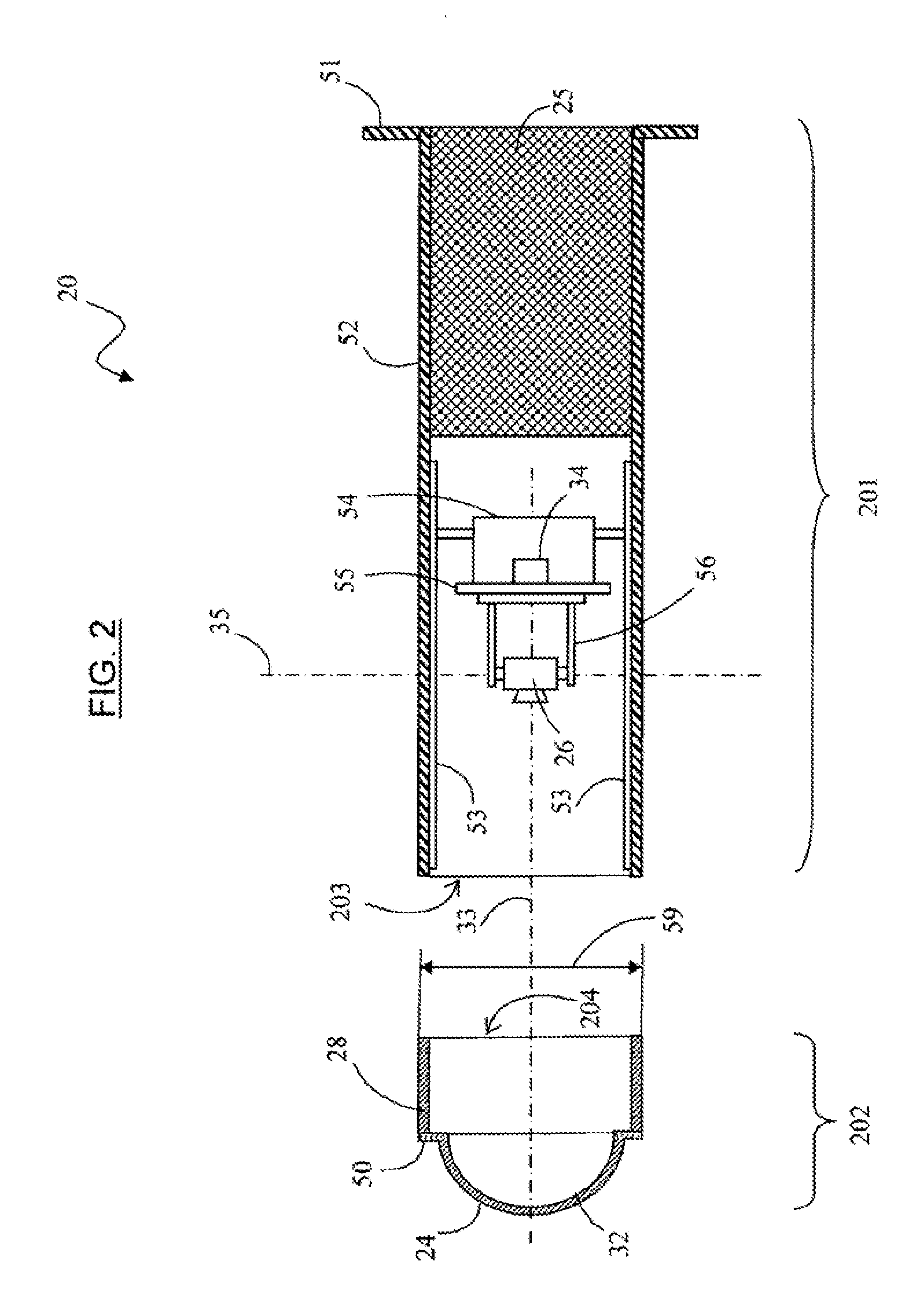
The invention provides a method of maintaining a cell including a wall pierced by a cavity fitted with a monitoring or observation instrument, the instrument comprising a dome projecting into the inside of the cell, a protection shield, an observation sensor arranged between the dome and the shield, and a travel mechanism for moving the sensor between a position retracted inside the cavity and a deployed position. The method comprises the following operations:
extracting the protection shield, the observation sensor, and the sensor travel mechanism out from the cavity, to the outside of the cell;
where appropriate, replacing the observation sensor;
inserting a replacement dome into the cavity and sliding it into the proximity of the dome that has remained in position in the cavity;
inserting the protection shield, the observation sensor and the sensor travel mechanism into the cavity and sliding them into contact with the replacement dome; and
moving the dome that has remained in position in the cavity until it is expelled into the inside of the cell, by pressing the replacement dome against the dome that has remained in position.

Description

TECHNICAL FIELD[0001]The present invention relates to an instrument for a hot cell, to a hot cell fitted with an instrument, and to a method of maintaining the instrument.[0002]The technical field of the invention is that of fabricating instruments for monitoring or observing the inside of a structure—or a compartment—that receives radioactive materials or substances.[0003]In the present application, the terms “cell” and “hot cell” are both used to designate such a structure.[0004]The present invention applies in particular to monitoring hot cells by acquiring images of zones situated in a hot cell, and by measuring the rays emitted in said zones, over wavelength-ranges that are visible or invisible for a human being.STATE OF THE ART[0005]A hot cell within which it is possible to store, manipulate, or otherwise process radioactive materials or substances generally comprises thick walls that form a biological protection shield to protect a person situated outside the cell from the ra...

Claims


Application Information

Patent Timeline
Patent Type & Authority Applications(United States)
IPC IPC(8): H04N7/18B23P6/00G01T1/00
CPCY10T29/4973G21F7/02
Inventor BLANCHARD, FRANCK
Owner COMMISSARIAT A LENERGIE ATOMIQUE ET AUX ENERGIES ALTERNATIVES
Why Eureka
Try Eureka