Observation Instrument Comprising A High-Resolution Image Recorder

a high-resolution, image-recording technology, applied in the field of observation instruments, can solve the problems of damage to the optoelectronic system, instruments could no longer be led through, etc., and achieve the effects of high numerical aperture, sharper or higher-resolution images, and large viewing angl

Active Publication Date: 2014-05-15
KARL STORZ GMBH & CO KG
View PDF27 Cites 9 Cited by
  • Summary
  • Abstract
  • Description
  • Claims
  • Application Information

AI Technical Summary

Benefits of technology

[0022]These measures have various advantages. The cylindrical section of the optical lens system can have or include such a size which suffices for still maintaining a sufficient interspace, be it a ring-shaped or a crescent-shaped interspace, in the hollow body.
[0047]This geometry allows an advantageous arrangement of the image sensor and an optimum utilization of the resolution thereof.

Problems solved by technology

The chemically aggressive media used in this case might damage the optoelectronic system.
This is impractical, however, since otherwise the interspace between the optoelectronic image recording system and the inner side of the hollow body would become small, and so instruments could no longer be led through or not enough optical fibres for the illumination could be led to distal.

Method used


Image

  • Observation Instrument Comprising A High-Resolution Image Recorder
  • Observation Instrument Comprising A High-Resolution Image Recorder
  • Observation Instrument Comprising A High-Resolution Image Recorder

Examples


Embodiment Construction

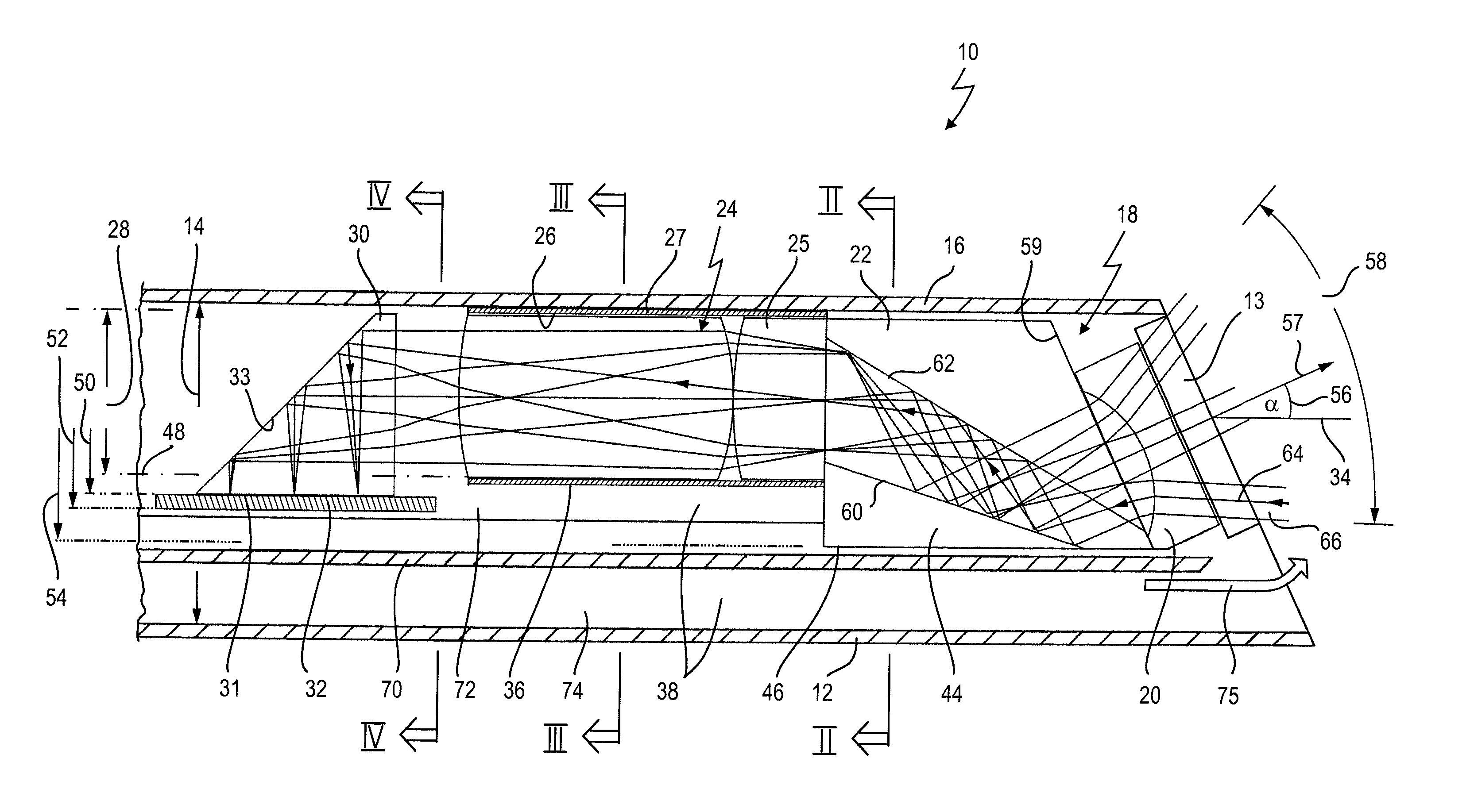
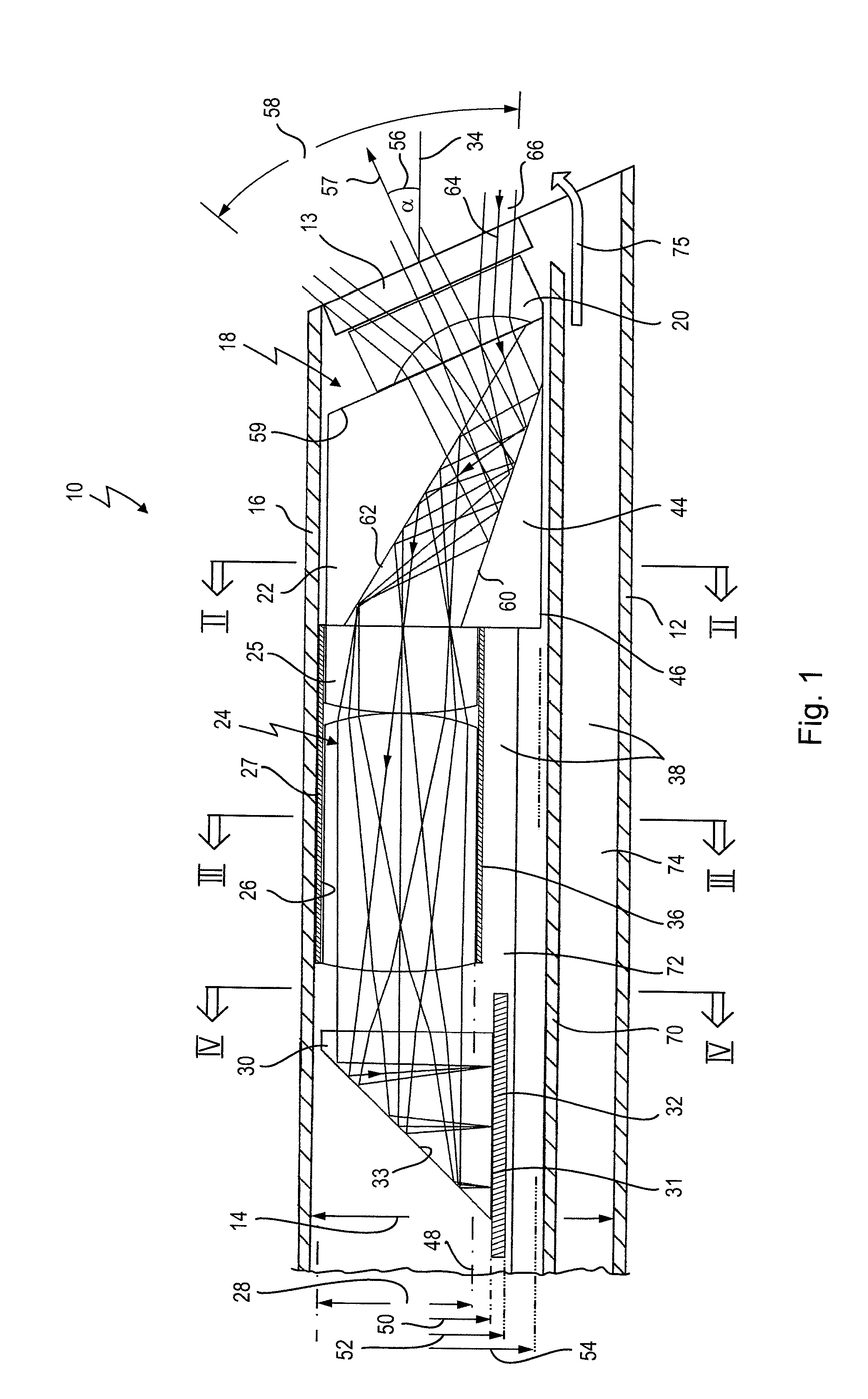
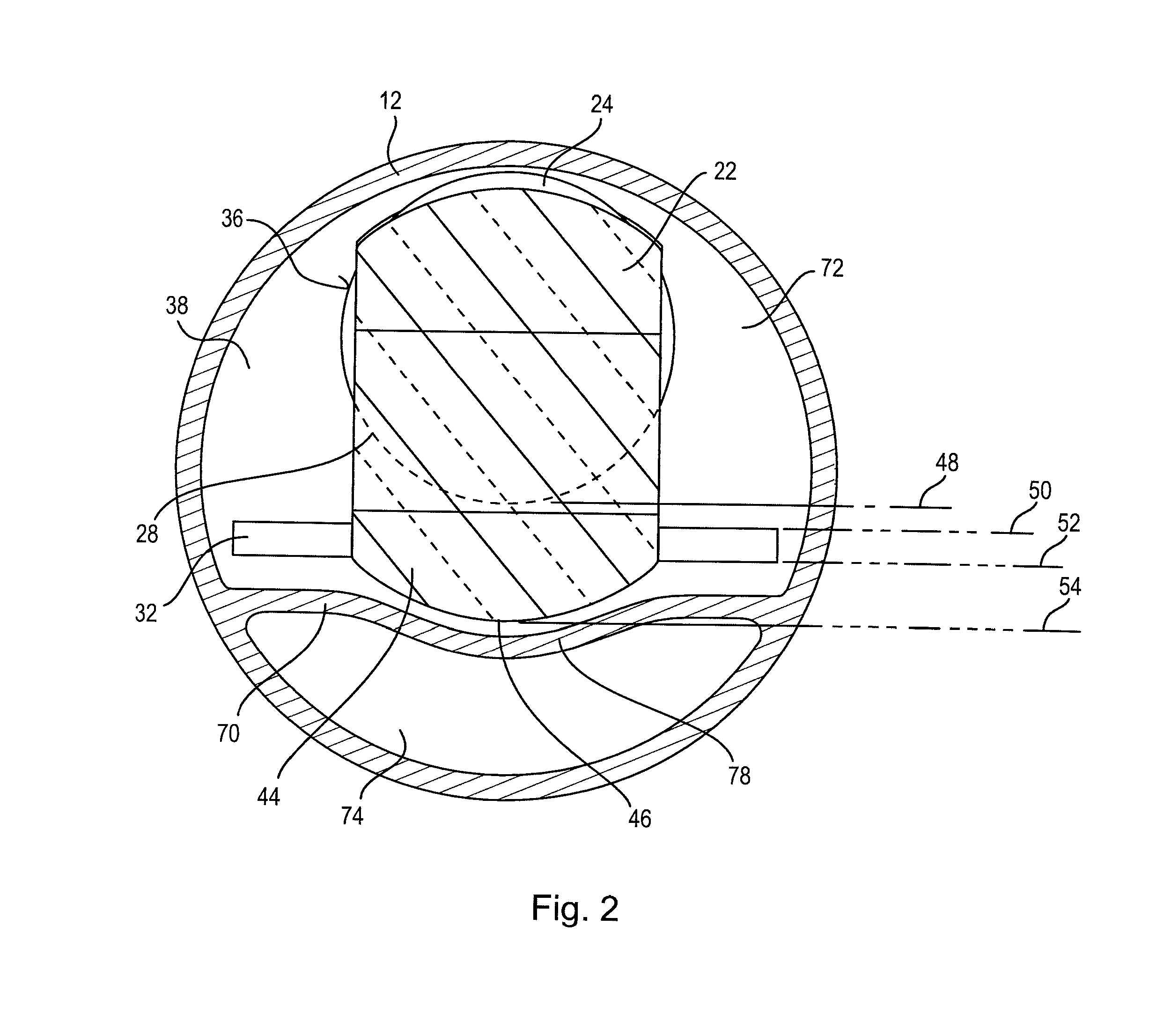
[0057]An exemplary embodiment of an observation instrument as illustrated in FIGS. 1 to 5 is designated in its entirety by the reference numeral 10.

[0058]The observation instrument 10 has a rectilinearly running stiff hollow body in the form of a hollow shank 12 having a specific internal diameter 14. The hollow body can be just a short stub or an elongated shank. The shank can be rigid or flexible. An optoelectronic image recording system 18 is accommodated in a distal end region 16 of the hollow shank 12. The hollow shank is closed off distally by means of a cover glass 13, which forms a sealing termination of the distal end of the hollow shank 12 by means of cement materials (not illustrated here). The cover glass 13 is transparent and thus allows entry of an observation light, that is an image which is to be acquired by the observation instrument 10.

[0059]The optoelectronic image recording system 18 has a negative lens 20, which on one side adjoins the inner side of the cover gl...


PUM


Abstract

An instrument includes a hollow body with an internal diameter and an optoelectronic image recording system, which is arranged in an end region of the body and has a lens system on an image entrance side. The lens system has a cylindrical section and an image sensor. An external diameter of the cylindrical section is less than the internal diameter of the body, such that an interspace remains between an inner side of the body and an outer side of the lens system, providing access in the body for components. With a viewing direction of 0° to 90° from the optical axis of the lens system, a deflection prism is arranged on the image entrance side at the lens system, and has a section extending laterally beyond the external diameter of the cylindrical section. An image entrance plane of the image sensor runs approximately parallel to the optical axis.

Description

BACKGROUND OF THE INVENTION[0001]The invention relates to an observation instrument comprising a hollow body having a specific internal diameter, wherein an optoelectronic image recording system is arranged in an end region of the hollow body and has on the image entrance side an optical lens system having a cylindrical section and subsequently an image sensor, which converts the image coming from the optical lens system into electrical image signals, wherein the optical axis of the lens system extends in the direction of the longitudinal axis of the hollow body, wherein the external diameter of the cylindrical section of the lens system is less than the internal diameter of the hollow body, to be precise such that between an inner side of the hollow body and the outer side of the optical lens system a sufficient interspace remains, through which further components can be led in the hollow body, wherein with a viewing direction of greater than 0° to less than 90° from the optical ax...

Claims


Application Information

Patent Timeline
Patent Type & Authority Applications(United States)
IPC IPC(8): A61B1/055
CPCA61B1/055A61B1/00096A61B1/00179G02B23/243G02B5/04
Inventor BAUMANN, HARALDREINACHER, JOACHIM
Owner KARL STORZ GMBH & CO KG
Why Eureka
Try Eureka