Radiant heat reflector and heat converter

Inactive Publication Date: 2011-03-03
REZNOR
View PDF30 Cites 5 Cited by
  • Summary
  • Abstract
  • Description
  • Claims
  • Application Information

AI Technical Summary

Problems solved by technology

A heating system of this type may warm objects or people on loading docks, near open doorways, or where conditions may cause a high heat loss.

Method used


Image

  • Radiant heat reflector and heat converter
  • Radiant heat reflector and heat converter
  • Radiant heat reflector and heat converter

Examples


Embodiment Construction

[0018]The following detailed description refers to the accompanying drawings. The same reference numbers in different drawings may identify the same or similar elements. The foregoing general description and the following detailed description are exemplary and explanatory only and are not restrictive of the invention, as claimed.

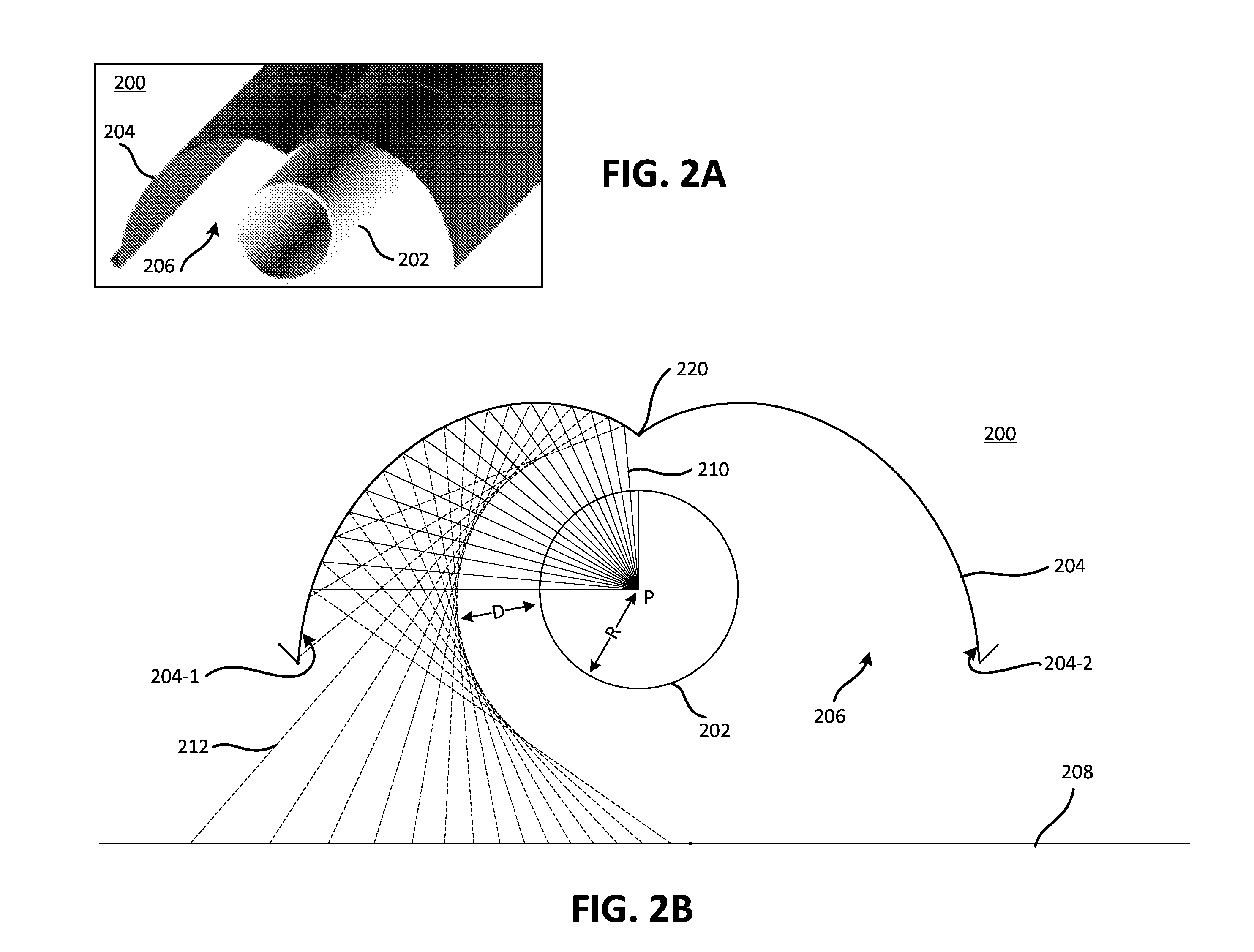
[0019]Embodiments described herein provide for a reflector to reflect heat radiated from a tube. One of these embodiments allows the reflected heat to avoid the tube itself, e.g., the reflected heat energy being directed around the tube rather than impinging on the tube. Other embodiments provide for a hood converter to capture heat, where the hood may radiate the captured heat.

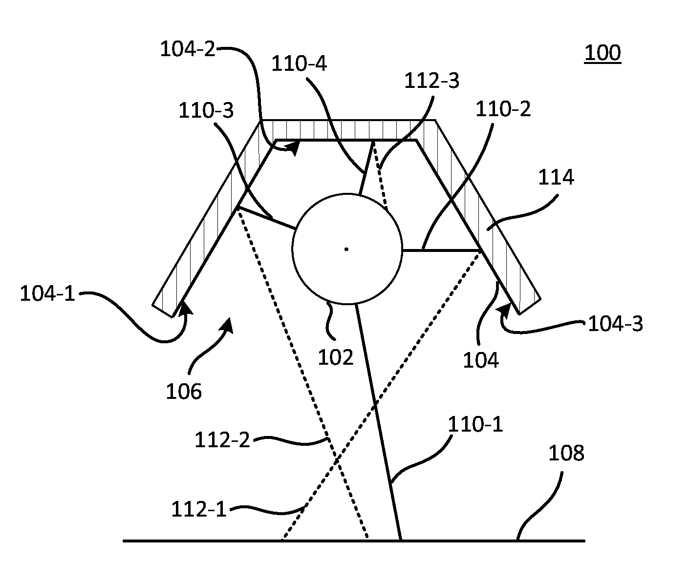
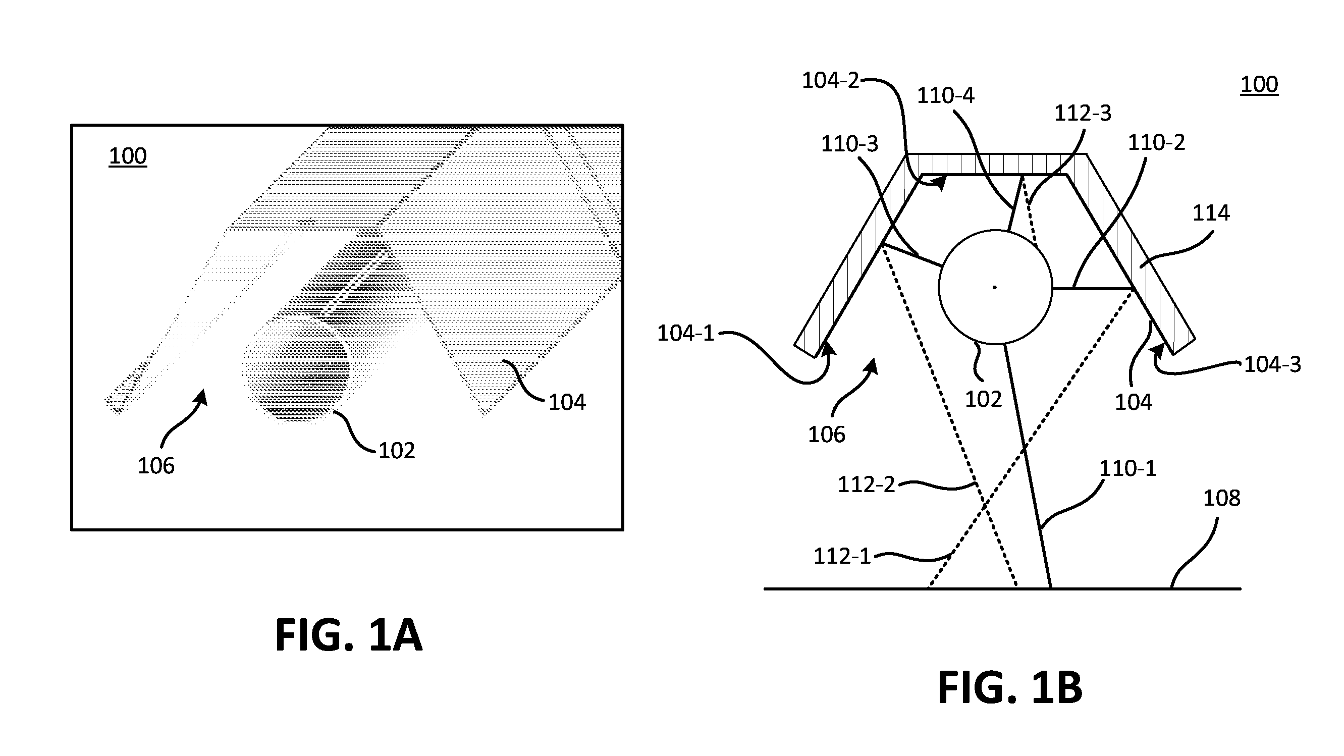
[0020]FIG. 1A is a diagram of a radiant heater 100. Radiant heater 100 may hang from a ceiling, for example, for the purpose of radiating heat downward toward a floor. FIG. 1B is a cross-sectional drawing of radiant heater 100 of FIG. 1A. Radiant heater 100 includes an emitting tube 1...


PUM


Abstract

A system may include a tube through which hot fluid is transported from one end to another, wherein the tube radiates heat energy and transfers heat energy to surrounding air by convection. The system may also include a reflector that reflects the radiated heat and a hood that captures the heat energy from the surrounding air through convection, wherein the hood radiates the captured heat energy. The reflector may include a bi-involute curved surface.

Description

RELATED APPLICATIONS[0001]This application claims the benefit of U.S. Provisional Patent Application No. 61 / 237,376 filed Aug. 27, 2009, which is hereby incorporated by reference.FIELD OF THE INVENTION[0002]Embodiments described herein relate to a radiant heater, and more particularly to a reflector and a heat converter in a radiant heater.BACKGROUND OF THE INVENTION[0003]Radiant heaters are frequently used in warehouses, factories, and commercial settings to provide a warm environment during cold weather. In such systems, tubular conduits (e.g., “tubes”) may hang from the ceiling or other overhead structure. A heated fluid (provided by a power plant) passes through the tube and heats the tube. The tube radiates heat waves (e.g., heat transfer by radiation) to an adjacent area, such as toward the floor. A reflector may direct the radiated heat in a desired direction. A heating system of this type may warm objects or people on loading docks, near open doorways, or where conditions ma...

Claims


Application Information

Patent Timeline
Patent Type & Authority Applications(United States)
IPC IPC(8): F24D3/00
CPCF24D5/08F24C15/22F24D3/02F24D19/062
Inventor CATTEAU, JEAN-PIERRECAPALDINI, GERALD
Owner REZNOR
Why Eureka
Try Eureka