High strength adjustable vertical concrete form

a concrete form, adjustable technology, applied in the direction of forms/shuttering/falseworks, other domestic objects, walls, etc., can solve the problems of heavy and labor-intensive assembly of reusable forms, high labor intensity of icf systems, and high labor intensity of reusable forms

Inactive Publication Date: 2011-03-10
TF FORMING SYST
View PDF21 Cites 52 Cited by
  • Summary
  • Abstract
  • Description
  • Claims
  • Application Information

AI Technical Summary

Problems solved by technology

Concrete walls for use in foundations, above grade walls, and the like have typically been constructed using expensive reusable forms.
These reusable forms, however, have typically been heavy and extremely labor-intensive to assemble.
Although effective, ICF systems are not without drawbacks.
Existing ICF system designs require parts that are formed by injection molding, which is an expensive process requiring expensive tooling.
Injection molding has also limited the practical length of the parts that can be produced to around nine feet.
These relatively short lengths increase labor costs by increasing the number of connections required in the assembly process.
Additionally, previous designs have g...

Method used


Image

  • High strength adjustable vertical concrete form
  • High strength adjustable vertical concrete form
  • High strength adjustable vertical concrete form

Examples


Embodiment Construction

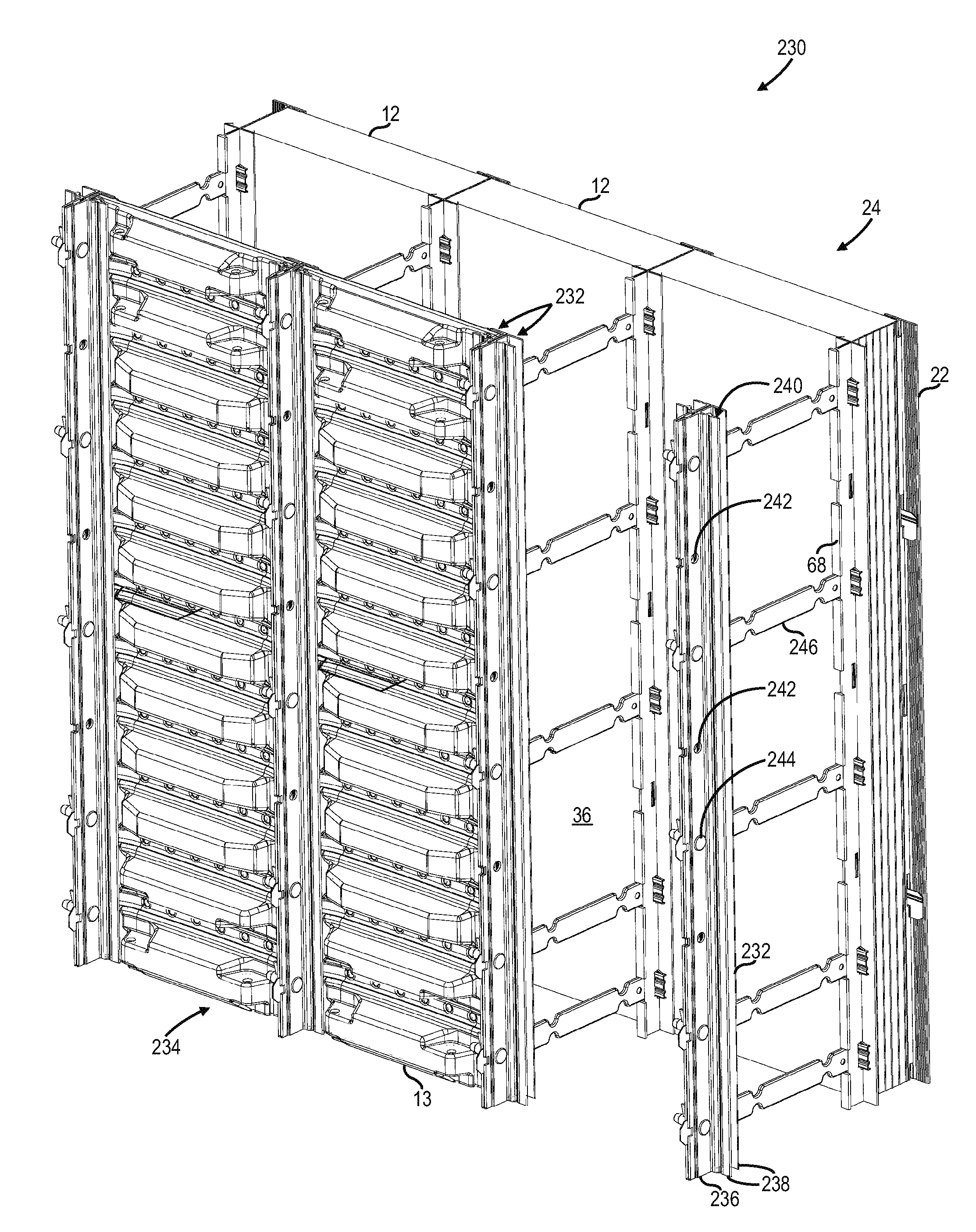
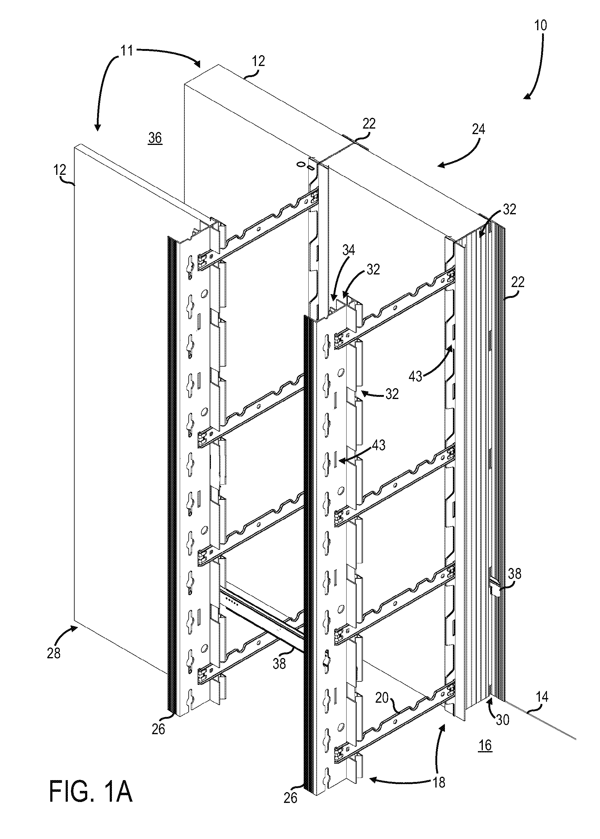
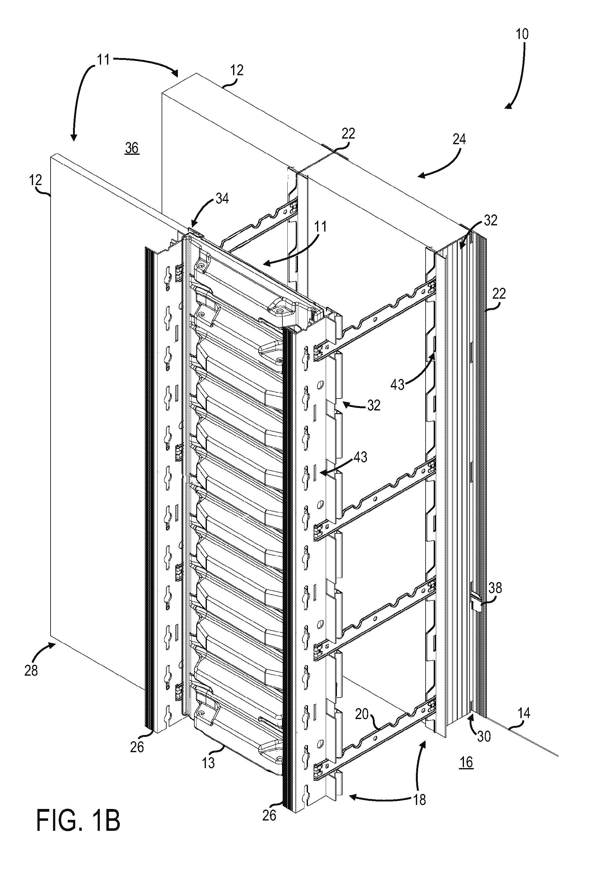
[0025]Referring to the drawings, a building form system 10 is shown in FIGS. 1A and 1B according to embodiments of the invention. The form system 10 is useful in construction and provides a form or mold for retaining concrete or other similar building materials until they harden to form a structural panel, foundation or the like. According to the embodiment of FIG. 1, the form system 10 provides two spaced, substantially parallel and substantially vertically oriented forming panels 11 between which concrete or other building material can be poured to form a structural member. According to embodiments of the invention, forming panels 11 can include insulating panels 12 and / or plastic support panels 13. It is envisioned that, according to embodiments of the invention, the forming panels 11 implemented by form system 10 may be in the form of both insulating panels 12 and plastic support panels 13, strictly insulating panels 12, or strictly plastic support panels 13. According to the em...


PUM


Abstract

A construction form system for forming concrete walls for use as above grade walls, foundations, frost walls, exterior envelopes, and the like, is disclosed. The system includes a plurality of pairs of opposing vertical forming panels spaced from each other to define a forming cavity disposed to receive a hardenable material. Each pair of opposing forming panels comprises an inner panel forming part of an inner wall and an outer panel forming part of an outer wall. The system also includes an outer rail positioned between each adjacent pair of outer forming panels and an inner rail positioned between each adjacent pair of inner forming panels. The inner forming panels comprise support panels configured to be selectively addable and removable from between each adjacent pair of inner rails prior to and subsequent to a pouring of the hardenable material into the cavity.

Description

BACKGROUND OF THE INVENTION[0001]Embodiments of the invention relate generally to building construction form systems and, more particularly, to a high strength, adjustable construction form system for forming concrete walls for use as above grade walls, foundations, frost walls, exterior envelopes, and the like.[0002]Concrete walls for use in foundations, above grade walls, and the like have typically been constructed using expensive reusable forms. In such systems, the forms maintain their proper position by a combination of metal tie plates between adjacent forms and metal tie rods between opposing forms. Such tie systems hold the forms in place during the assembly of the forming system and resist the movement of the forms from their proper alignment positions when concrete or other hardenable materials are poured and worked between the forms. After the concrete or other materials are hardened and at least partially cured, the conventional forms are typically removed from the stru...

Claims


Application Information

Patent Timeline
IPC IPC(8): E04G11/06E04G15/02
CPCE04B2/8652E04B2002/867E04B2002/8688B29D99/001E04G17/002E04G17/047E04G11/06E04G11/14E04G2017/0646E04G9/10E04B2002/8682E04G2011/067
Inventor SPUDE, GERALD T.HUFF, STEVEN T.DANNER, BRYAN L.
Owner TF FORMING SYST
Why Eureka
Try Eureka