External ranging image pickup apparatus and ranging method

Inactive Publication Date: 2011-03-10
CANON KK
View PDF7 Cites 13 Cited by
  • Summary
  • Abstract
  • Description
  • Claims
  • Application Information

AI Technical Summary

Benefits of technology

[0007]The present invention provides an external ranging image pickup apparatus ca

Problems solved by technology

The parallax displaces a ranging area where ranging (object distance measurement) is performed by the external ranging sensor

Method used


Image

  • External ranging image pickup apparatus and ranging method
  • External ranging image pickup apparatus and ranging method
  • External ranging image pickup apparatus and ranging method

Examples


embodiment 1

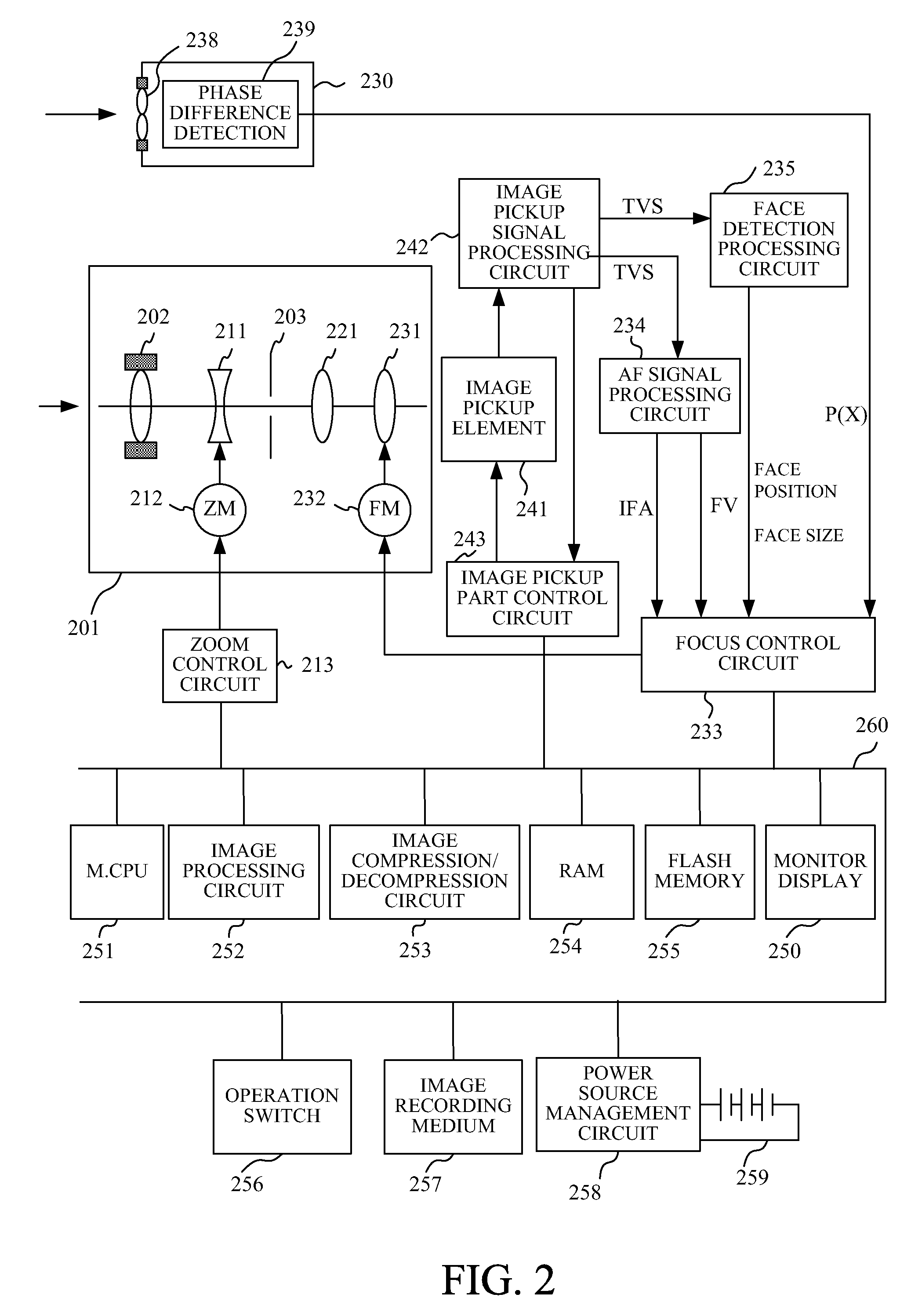
[0044]FIG. 2 shows a configuration of a camera (image pickup apparatus) that is a first embodiment (Embodiment 1) of the present invention, such as a video camera and a digital camera. The configuration of this camera is common to that of a second embodiment (Embodiment 2) described later.

[0045]Respective units in the camera are mutually connected through a bus 260, and controlled by a main CPU 251.

[0046]A lens unit 201 that is an image taking optical system includes, in order from an object side to an image plane side in an optical axis direction, a fixed front lens 202, a zoom lens 211, an aperture stop 203 and a fixed third lens 221 and a focus lens 231. Light from an object passes through the lens unit 201 to form an optical object image on an image pickup element 241. The image pickup element 241 photoelectrically converts the optical object image to output an electric signal.

[0047]A zoom control circuit 213 drives a zoom motor 212 according to an instruction from the main CPU ...

embodiment 2

[0110]A flowchart of FIG. 16 shows ranging area selection processing in the second embodiment (Embodiment 2) of the present invention. This ranging area selection processing is performed at step S707 in FIG. 7 in place of the ranging area selection processing shown in FIG. 11. Constituent elements of a camera of this embodiment are common to those of the camera of Embodiment 1, and therefore these constituent elements are denoted by the same reference numerals as those in Embodiment 1.

[0111]After starting the processing at step S1601, the controller determines at step S1602 whether or not a face included in image data has moved in an in-plane direction of an image pickup plane (that is, in a direction parallel to a light-receiving surface of an image pickup element 241) or in an optical axis direction (that is, a direction orthogonal to the light-receiving surface of the image pickup element 241). This determination can be made by comparing a position and a size of a face area previ...


PUM


Abstract

The image pickup apparatus includes a first detection unit detecting information corresponding to an object distance in each of plural areas, without through an image taking optical system, a second detection unit detecting a size and a position of a specific object area in object image data, and a controller performing focus control of the image taking optical system on the basis of the information corresponding to the object distance. The controller acquires specific object distance information on a distance to a specific object, on the basis of the size of the specific object area and information on a focal length of the image taking optical system, and selects, from the plural areas, an area where the information corresponding to the object distance to be used in focus control is detected, on the basis of the specific object distance information and the position of the specific object area.

Description

BACKGROUND OF THE INVENTION[0001]The present invention relates to an image pickup apparatus provided with a ranging sensor outside an image pickup optical system.DESCRIPTION OF THE RELATED ART[0002]Some auto-focus functions equipped with image pickup apparatuses such as digital cameras detect a focus state of an image taking optical system by detecting a phase difference of two optical object images formed by the image taking optical system or by detecting high-frequency components of image data generated by photoelectric conversion of an optical object image. Other some auto-focus functions, which are different from the above-described internal focus detection systems, are external ranging systems measuring an object distance by using a ranging sensor provided outside the image taking optical system (hereinafter referred to as an “external ranging sensor”), that is, without through the image taking optical system.[0003]In the external ranging system, a parallax is generated between...

Claims


Application Information

Patent Timeline
IPC IPC(8): G03B13/20
CPCG03B13/20
Inventor MIZUO, YOSHIHIRO
Owner CANON KK
Why Eureka
Try Eureka