Method for production of high purity distillate from produced water for generation of high pressure steam

a high-purity distillate and produced water technology, which is applied in the direction of separation processes, well accessories, insulation, etc., can solve the problems of contaminating the distillate quality, affecting the production efficiency of high-purity distillates, etc., to achieve the effect of reducing or eliminating the need for downbore wastewater disposal, reducing operating pressure, and reducing the need for adsorption

Active Publication Date: 2011-03-17
AQUATECH INT LLC
View PDF8 Cites 20 Cited by
  • Summary
  • Abstract
  • Description
  • Claims
  • Application Information

AI Technical Summary

Benefits of technology

[0012]Embodiments provided herein may overcome the limitations caused by dissolved solids in the distillate produced by the conventional MVC evaporation system. A high purity distillate

Problems solved by technology

Unfortunately, the current approaches to produced water purification and distillate production have drawbacks and disadvantages that hinder achievement of desired distillate purity in a cost-effective manner.
The current practice of disposing of wastewater by injecting in a deep well formation in heavy oil facilities is also not a very environmentally prudent approach.
The droplets that are entrained in this water vapor tend to remain entrained and mix with the condensed vapor to contaminate the distillate quality.
The internal demister offers only one stage of droplet elimination; therefore, the process is limited in the distillate purity that may be achieved.
This underachievement limits the use of this distillate.
Drum boilers must be designed and operated at lower pressures because of this deficiency.
OTSGs are also limited in the vaporization rate they can achieve.
Further problems ensue for the conventional purification technology because of

Method used


Image

  • Method for production of high purity distillate from produced water for generation of high pressure steam
  • Method for production of high purity distillate from produced water for generation of high pressure steam
  • Method for production of high purity distillate from produced water for generation of high pressure steam

Examples


example 1

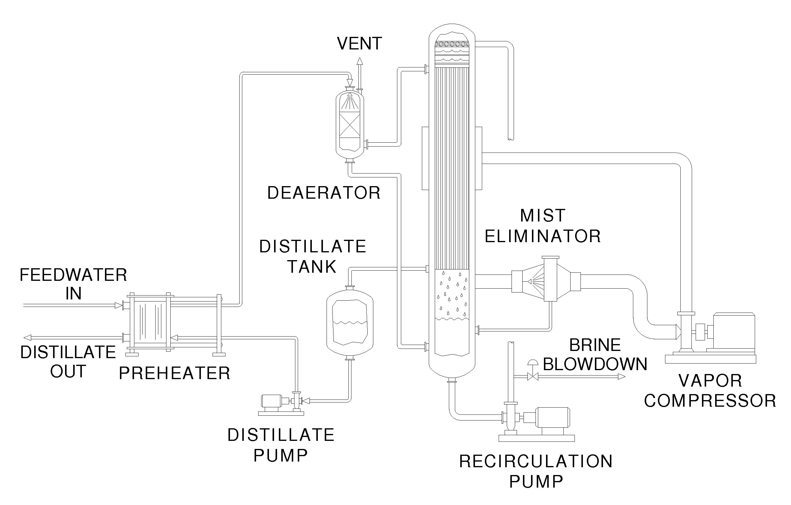
[0050 describes performance of an evaporation system treating produced water by generating high quality distillate. A pilot scale test was run on a representative sample of produced water from a SAGD process to ascertain the effectiveness of several design enhancements. The objectives were 1) to prove the effectiveness of softening the produced water upstream of the evaporator and 2) to prove that straight-sump falling film evaporator design could process a high amount of oil and grease. Of course, the satisfaction of these test objectives should not be viewed as a requirement for an embodiment to be within the scope of the claims. The total run time of the pilot testing was 972 hrs. The evaporator system was operated at a concentration factor of 26 for a net recovery of 96%.

[0051]The process stages included produced water softening reactor, produced water preheater, deaerator, vertical-tube falling film evaporator (straight-sump), multiple-stage mist elimination, and a final vapor ...

example 3

[0055 reports the deficiency of the wide-sump design in that a quiescent volume is generated that leads to stagnation and accumulation of oil and hydrocarbons. A computation fluid dynamic study (FIG. 9) was undertaken to determine the effectiveness of an evaporator wide-sump to provide good mixing and prevent the creation of stagnant pockets. The results of the study show that the wide-sump does, in fact, create a quiescent volume in the annular region of the sump. The fluid velocities in this annular region range from approximately 0 feet per second to 1 feet per second. In the chamber, the fluid circulates counterclockwise from the bottom to the top. The recirculating velocities within the side chamber are very small and indicate very little mixing and very little new flow of liquid into this section of the tank. In contrast to the wide-sump, the straight-sump evaporator simulates fluid flow in a pipe and has a relatively uniform velocity profile that precludes the creation of sta...


PUM

PropertyMeasurementUnit
Temperatureaaaaaaaaaa
Fractionaaaaaaaaaa
Fractionaaaaaaaaaa

Abstract

Embodiments presented herein provide an evaporation based zero liquid discharge method for generation of up to 100% quality high pressure steam from produced water in the heavy oil production industry. De-oiled water is processed in an evaporation system producing a distillate that allows steam to be generated with either drum-type boilers operating at higher pressures or once-through steam generators (OTSGs) operating at higher vaporization rates. Evaporator blowdown is treated in a forced-circulation evaporator to provide a zero liquid discharge system that could recycle>98% of the deoiled water for industrial use. Exemplary embodiments of the invention provide at least one “straight sump” evaporator and at least one hybrid external mist eliminator. Embodiments of the evaporation method operate at a higher overall efficiency than those of the prior art by producing distillate at a higher enthalpy which minimizes the high pressure boiler preheating requirement.

Description

CROSS-REFERENCE TO RELATED APPLICATIONS[0001]This application claims priority to U.S. provisional patent application No. 61 / 232,067, filed on Aug. 7, 2009, and incorporated by reference herein.BACKGROUND OF THE INVENTION[0002]1. Field of the Invention[0003]Embodiments of the invention relate to methods and apparatuses for generation of high-quality high pressure steam from produced water in the heavy oil production industry.[0004]2. Description of the Related Art[0005]Heavy oil recovery processes employ the “steamflood” technique, in which steam is injected to the oil bearing formations to improve the recovery of heavy oils. Typically, several units of steam are required for recovering each unit of oil. Heavy oil is a viscous fluid, and the heat from steam reduces the viscosity of the oil allowing it to flow to a production well. In the process of heating the oil, steam condenses. This condensed steam is called produced water. The mixture of oil and produced water is pumped to the s...

Claims


Application Information

Patent Timeline
IPC IPC(8): E21B43/24
CPCE21B41/0057F01K15/00E21B43/40E21B43/24Y02P80/15E21B43/35
Inventor BJORKLUND, DANIEL P.MANDIGO, GREGORY J.SCHOEN, RICHARD M.MARLETT, JAMES MICHAELTIWARI, CHANDRAKANT
Owner AQUATECH INT LLC
Why Eureka
Try Eureka