
3D Autostereoscopic Display System With Multiple Sets Of Stereoscopic Views

a display system and stereoscopic technology, applied in the field of projection/display systems, can solve the problems of narrow or restricted viewing area, inconvenient or possible for viewers to wear special eyeglasses, and inability to achieve advanced auto-stereoscopic viewing techniques

Inactive Publication Date: 2011-03-17
NELSON BRADLEY +2
View PDF6 Cites 16 Cited by
  • Summary
  • Abstract
  • Description
  • Claims
  • Application Information

AI Technical Summary

Benefits of technology

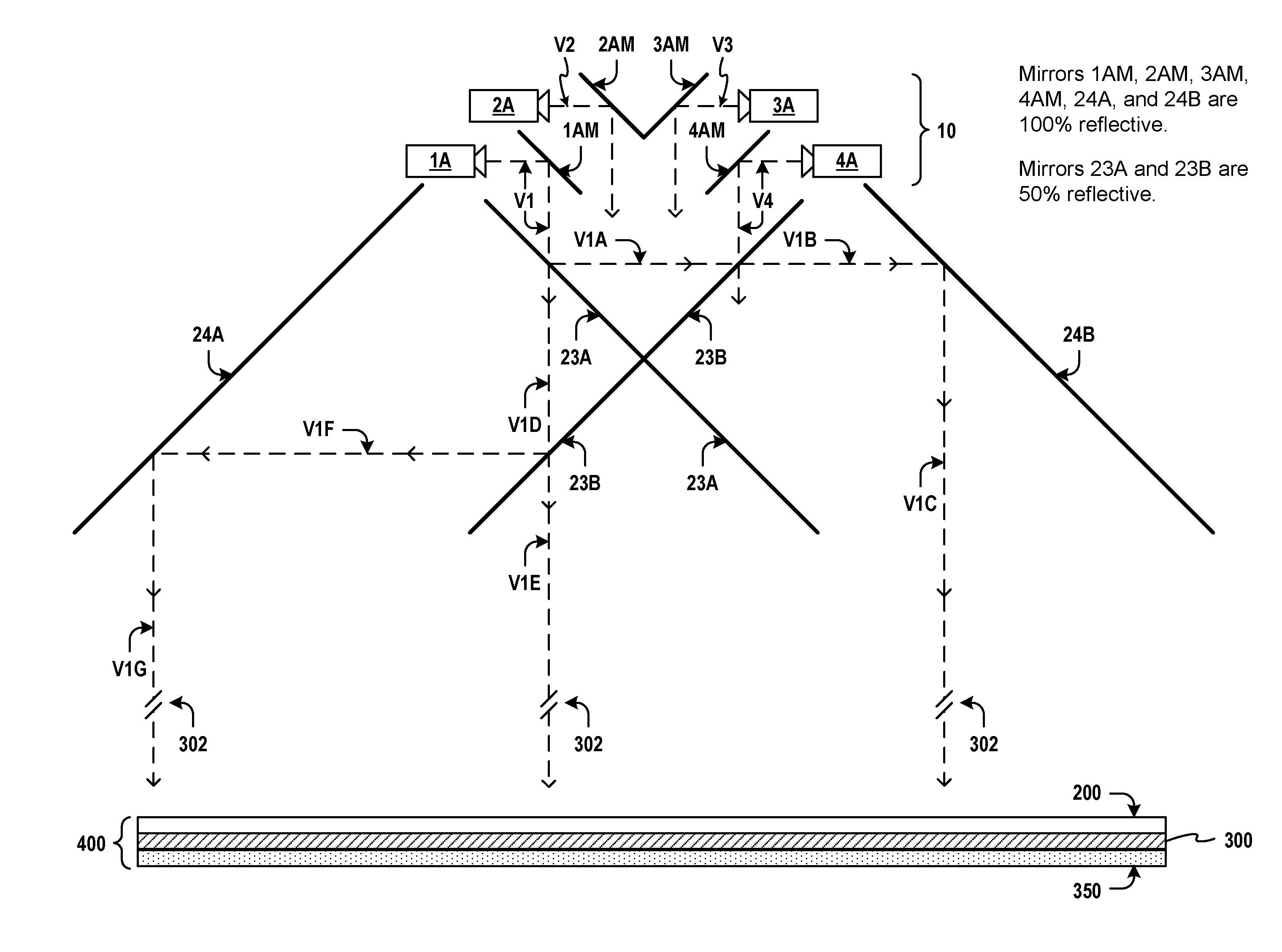
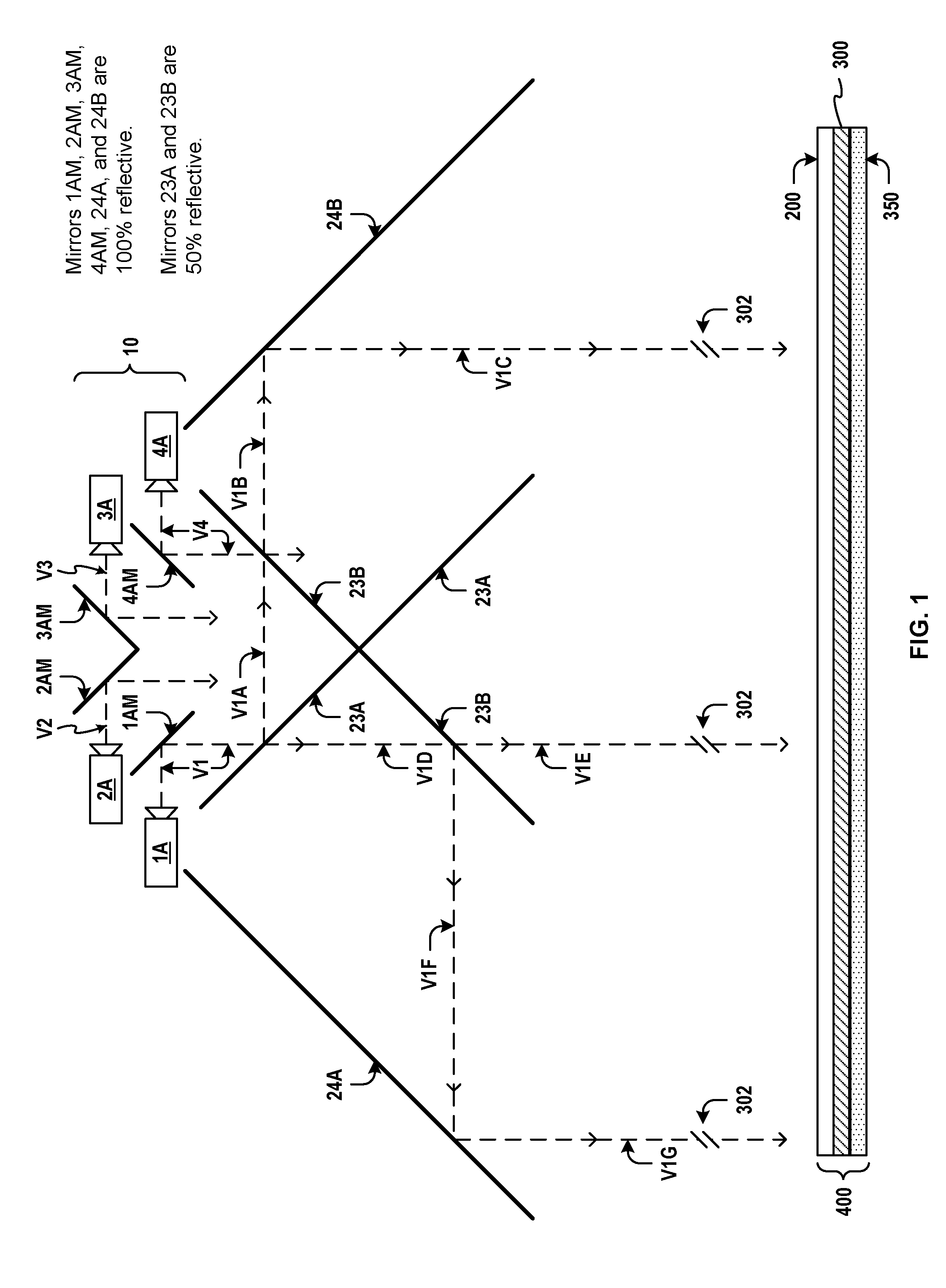
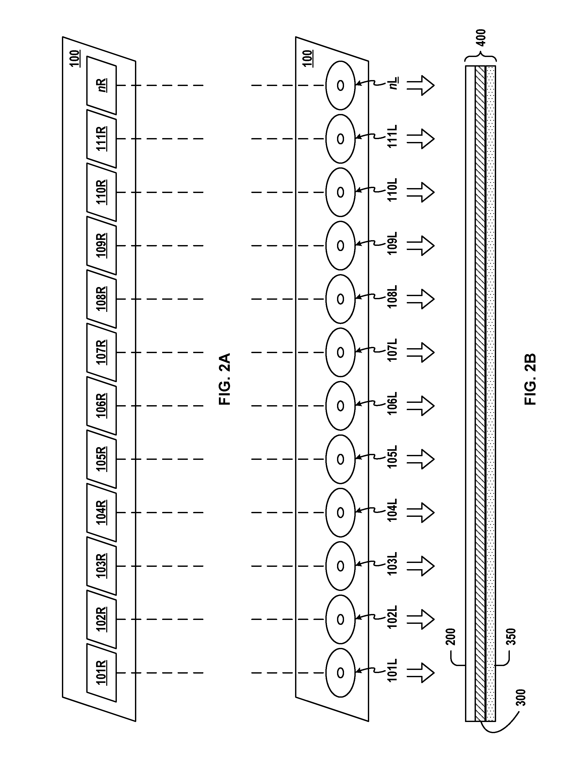
[0007]Methods and techniques project autostereoscopic scenes into free space viewports—out of and beyond the confines of a projection enclosure. Multiple sets of view channels originate from multiple projected views modulated through an optic assembly comprising a Fresnel lens, a vertical dispersion lenticular lens, and a diffuser. Compact projection enclosures are formed using image-repeating mirrors to create a three-dimensional autostereoscopic viewing experience in free space without the use of special eyeglasses and without the use of view screens. Multiple sets of images are r...

Problems solved by technology

However, it may not be convenient or possible for a viewer to wear such special eyeglasses, thus more advanced techniques for auto-stereoscopic viewing are needed.
However, such techniques presented a narrow or restricted viewing area confined within an enclosure that housed the two lenses.
Moreover such convex lens-based configurations failed to provide a means of providing a separate viewing channel for each eye.
Also, such configurations are not well suited for viewing in large venues.

Method used


Image

  • 3D Autostereoscopic Display System With Multiple Sets Of Stereoscopic Views
  • 3D Autostereoscopic Display System With Multiple Sets Of Stereoscopic Views
  • 3D Autostereoscopic Display System With Multiple Sets Of Stereoscopic Views

Examples


Embodiment Construction

[0023]The following detailed description is directed to certain specific embodiments of the invention. However, the invention can be embodied in a multitude of different ways as defined and covered by the claims and their equivalents. In this description, reference is made to the drawings wherein like parts are designated with like reference characters throughout.

[0024]Stereoscopic display systems may generally be divided into two categories. In the first category, two views or view channels are projected. The two view channels are then segregated after traveling to the observer by use of polarized or other special eyeglasses worn by the observer. In such embodiments in this first category, eyeglasses comprised of colored filters would segregate projections of images coded using different colors. In other embodiments in this first category, circular polarized lenses are used by observers (possibly using special polarized lens eyeglasses worn by the observer) to separate view channel...


PUM


Abstract

Multiple sets of view channels originate from multiple projected views modulated through an optic assembly comprising a Fresnel lens, a vertical dispersion lenticular lens, and a diffuser. Compact projection enclosures are formed using image-repeating mirrors to create a three-dimensional autostereoscopic viewing experience in free space without the use of special eyeglasses and without the use of view screens. Multiple sets of images are repeated within a viewing zone that may extend well beyond the confines of the enclosure and may be projected through and beyond a glass window. An observer walking past the window will see one view channel per eye, due in part to the repeated images, and due in part to the vertical dispersion of each projected view. Separate images for each view channel may be created by using two or more cameras spaced apart at a distance interval to match the average horizontal distance between the eyes of a human observer. Multiple views or multiple sets of view channels may be generated and projected.

Description

[0001]This application claims priority, under 35 U.S.C. §119(e), to U.S. Provisional Application No. 61 / 218,198 filed Jun. 18, 2009, which is expressly incorporated herein by reference.FIELD OF THE INVENTION [0002]The present invention generally relates to projection / display systems. More particularly, the invention relates to multiple projection views that are modulated for producing 3D autostereoscopic effects.BACKGROUND [0003]Imagine strolling down the sidewalk in a metropolis, passing a window display such as a “window shopping” display attraction that a major department store would provide. Imagine that the window display attraction, instead of being lighted by ambient light, were a scene brilliantly projected into your eyes. Imagine the scene changes realistically as you stroll further past the window display. Further imagine that the scene appears in every regard to be in three dimensions, and that the perspective perceived by your eyes changes realistically as you walk past ...

Claims


Application Information

Patent Timeline
IPC IPC(8): G02B27/22H04N13/363
CPCH04N13/0459H04N13/0404H04N13/305H04N13/363
Inventor NELSON, BRADLEYNOBLE, LOWELL A.ASMUSSEN, MELLISSA NOBLE
Owner NELSON BRADLEY
Learn More