
Compact light emitting diode retrofit lamp and method for traffic signal lights

a technology of light-emitting diodes and lamps, which is applied in the direction of identification means, ways, instruments, etc., can solve the problems of disrupting traffic flow through intersections, time-consuming and labor-intensive removal of reflectors and sockets, and inability to put the original incandescent lamps back in the traffi

Inactive Publication Date: 2005-06-28
LEOTEK ELECTRONICS
View PDF29 Cites 72 Cited by
  • Summary
  • Abstract
  • Description
  • Claims
  • Application Information

AI Technical Summary

Benefits of technology

[0012]The present invention solves the aforementioned problems by providing an LED lamp and method for retrofitting conventional traffic signal lamps, without having to remove or utilize the reflectors therein.

Problems solved by technology

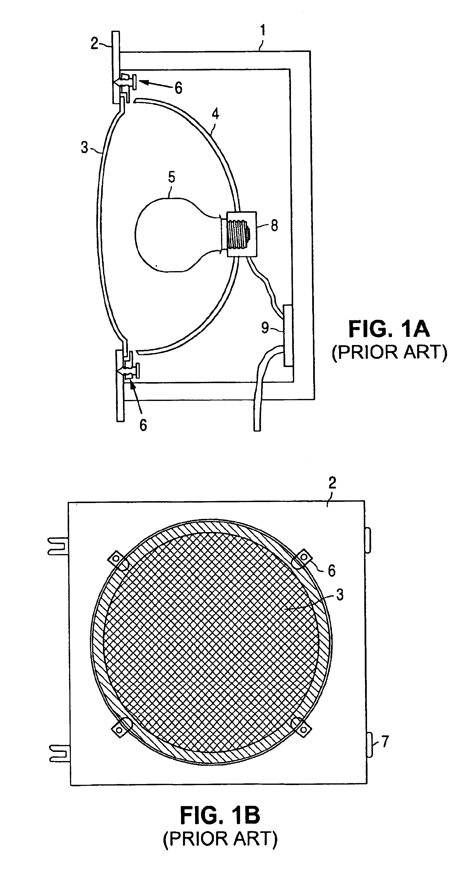
First, it is time consuming and labor intensive to remove the reflector and socket, and access the terminal strip with new wiring.
Second, in order to safely disconnect the socket connector wires from the terminal strip, and connect new wires from the LED lamp module to the terminal strip, the power to the traffic signal must be temporarily turned off, which disrupts traffic flow through the intersection.
Finally, once the retrofit is complete, it is not possible to put the original incandescent lamp back in the traffic signal lamp, for example, in case a spare LED lamp module is not available.
This LED lamp can be easily substituted for a conventional traffic light bulb, but the intensity from such a lamp can be problematic.
Not only is it difficult to mount enough LEDs on the spherical lamp head to produce the desired luminosity, but light emanating therefrom must still reflect off of the reflector, which can be optically lossy and degrade over time.
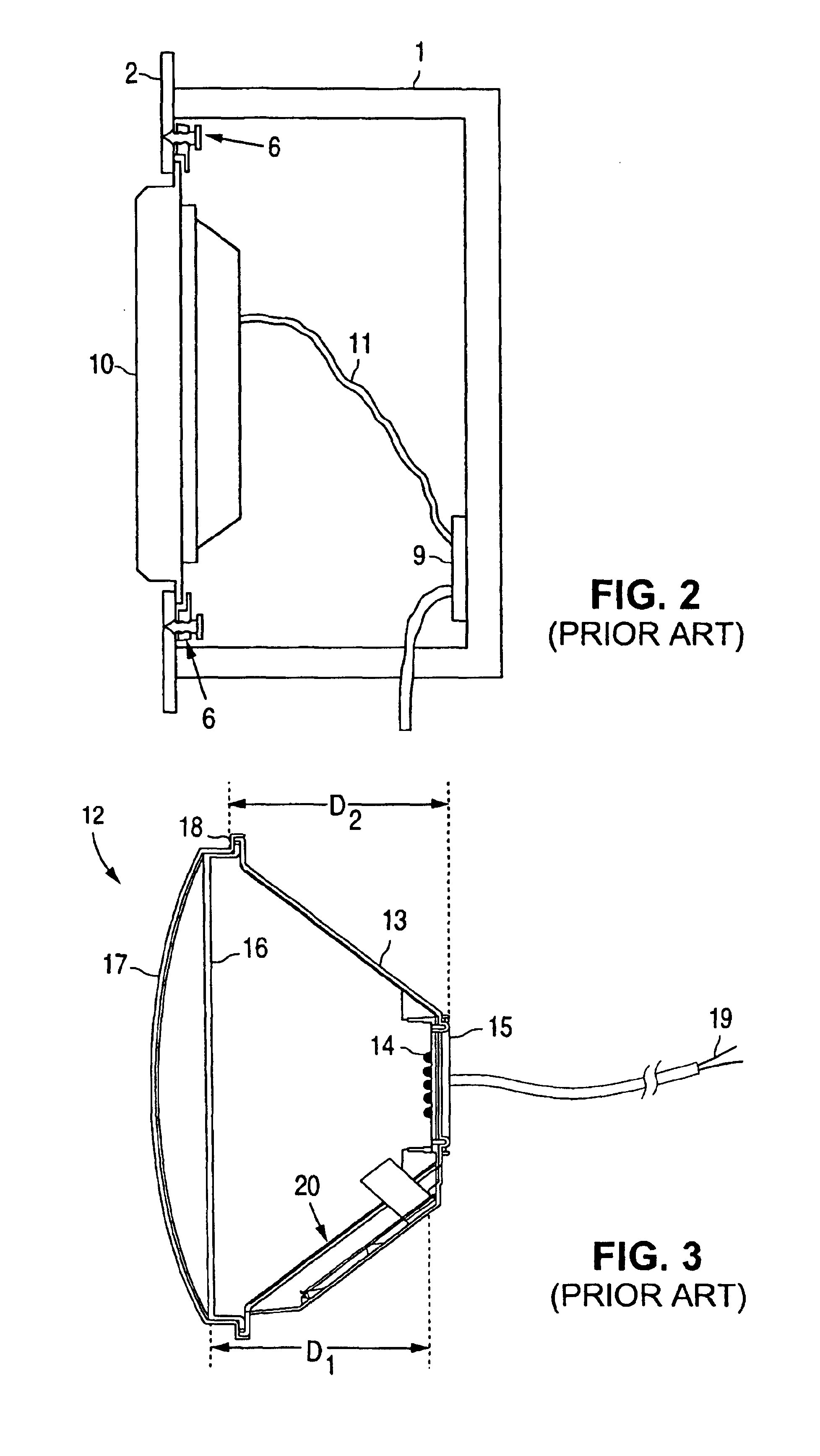
Thus, the installation of the Dialight lamp is cumbersome and time consuming because it requires removal of the existing traffic signal lamp reflector, electrical socket, and electrical connection to the terminal strip.

Method used


Image

  • Compact light emitting diode retrofit lamp and method for traffic signal lights
  • Compact light emitting diode retrofit lamp and method for traffic signal lights
  • Compact light emitting diode retrofit lamp and method for traffic signal lights

Examples


Embodiment Construction

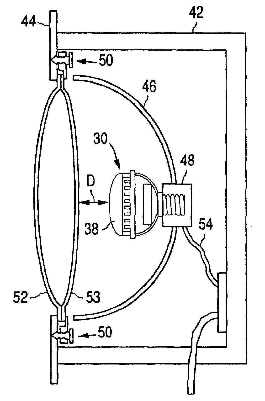
[0023]The present invention is a compact, light weight LED lamp and lens set for retrofitting traffic lights using conventional incandescent light bulbs, lenses and reflectors.

[0024]The high power LED lamp 30 according to the present invention is illustrated in FIG. 4, and includes a housing 32, an array of high power LEDs 34 mounted inside the housing 32 preferably on a substantially planar mounting surface (e.g. PC board) 35 for producing a diverging light output, a power supply 36 disposed in the housing for supplying electrical power to the LEDs 34, and a threaded electrical connector 40 extending from the housing 32 and electrically connected to the power supply 36. The housing 32 includes an optical lens 38 disposed over the LEDs 34, to protect the LEDs and possibly focus down or expand the diverging light therefrom.

[0025]FIG. 5 illustrates a conventional traffic signal lamp retrofitted with the LED lamp 30 of the present invention. The retrofitted traffic signal lamp includes...


PUM


Abstract

A high power LED lamp and method for retrofitting conventional traffic signal lamps. The LED lamp includes a housing, a power supply disposed in the housing, a plurality of LEDs mounted to a substantially planar mounting surface in the housing and electrically connected to the power supply for producing diverging light, and a threaded electrical connector extending from the housing. The method includes replacing a conventional incandescent light bulb with the LED lamp, and installing a Fresnel lens inside the traffic signal lamp that collimates and just fills and illuminates the outer lens of the traffic signal lamp.

Description

[0001]This application claims the benefit of U.S. Provisional Application No. 60 / 408,258, filed Sep. 4, 2002, and entitled Compact Light-Emitting Diode (LED) Retrofit Lamp For Traffic Signal Lights.FIELD OF THE INVENTION[0002]The present invention relates to Light-Emitting Diode (LED) lamps for traffic signal lamps, and more particularly to an improved compact LED lamp retrofit lamp for replacing conventional light bulbs in traffic signal lamps, including 12 and 8 inch round traffic signal lamps, pedestrian signs, hand signs, arrow signs and signs with messages.BACKGROUND OF THE INVENTION[0003]Light emitting diode (LED) lamps have been developed to replace conventional incandescent or fluorescent lamps for reducing electrical and maintenance costs, and for increasing reliability. LED lamps consume less electrical energy than conventional lamps while exhibiting much longer lifetimes. Such LED lamps typically include a power supply and a plurality of LEDs mounted on a flat or curved s...

Claims


Application Information

Patent Timeline
IPC IPC(8): B61L5/00B61L5/18F21V5/04F21V5/00F21K7/00G08G1/095F21S8/00F21S2/00F21K99/00F21S8/10F21Y101/02
CPCB61L5/1854F21V5/045G08G1/095F21K9/135B61L2207/02F21W2111/00F21W2111/02Y02B20/383F21V23/001F21Y2101/02B61L5/1845F21K9/232F21Y2115/10Y02B20/30
Inventor WU, CHEN H.BACILIERI, STEVEWANG, CHAO SUNGWANG, SHIH CHANG
Owner LEOTEK ELECTRONICS
Learn More