Concentrating type solar collection and daylighting system within glazed building envelopes

a solar collector and daylighting technology, applied in the field of multi-functional systems, can solve the problems of large amount of silicon required, hampered widespread adoption of solar powered systems for general use, and inability to meet the requirements of flat plate technology

Active Publication Date: 2007-03-13
RENESSELAER POLYTECHNIC INST
View PDF8 Cites 74 Cited by
  • Summary
  • Abstract
  • Description
  • Claims
  • Application Information

AI Technical Summary

Problems solved by technology

Although these technologies work, widespread adoption of these solar powered systems for general use has been hampered by a number of impediments.
The viability of the flat plate technology is hindered by the large amount of silicon required in the manufacture of the system.
This results in a very expensive system.
Within the current market structure, these systems are both dependent on scrap discards from the semiconductor industry, as well as on large government subsidies for their implementation—both circumstances constitute economic impediments for a growing industry.
Furthermore, even with substantial subsidies, large flat-plate silicon PV panels have been difficult to market because they have been perceived by consumers as unsightly and / or inappropriate for most building types.
The viability of the ‘stand-alone’ concentrating PV systems has been hindered by the cost and the appearance of the large tracking structures 2 (see FIG. 2) required for their implementation.
This not only increases the cost payback period, it excludes them from application to sites which would most benefit from their energy production.
That is, the enormous and unsightly appearance of the structures substantially limits their potential for widespread application to building properties.
Furthermore, the stand alone concentrating PV systems suffer from wind loading effects due to their large size.
Additionally, both of the conventional systems suffer from relatively weak ‘solar to electric’ operating conversion efficiencies.
Furthermore, the remaining 80%–87.5% energy is generally lost as wasted heat.

Method used


Image

  • Concentrating type solar collection and daylighting system within glazed building envelopes
  • Concentrating type solar collection and daylighting system within glazed building envelopes
  • Concentrating type solar collection and daylighting system within glazed building envelopes

Examples


Embodiment Construction

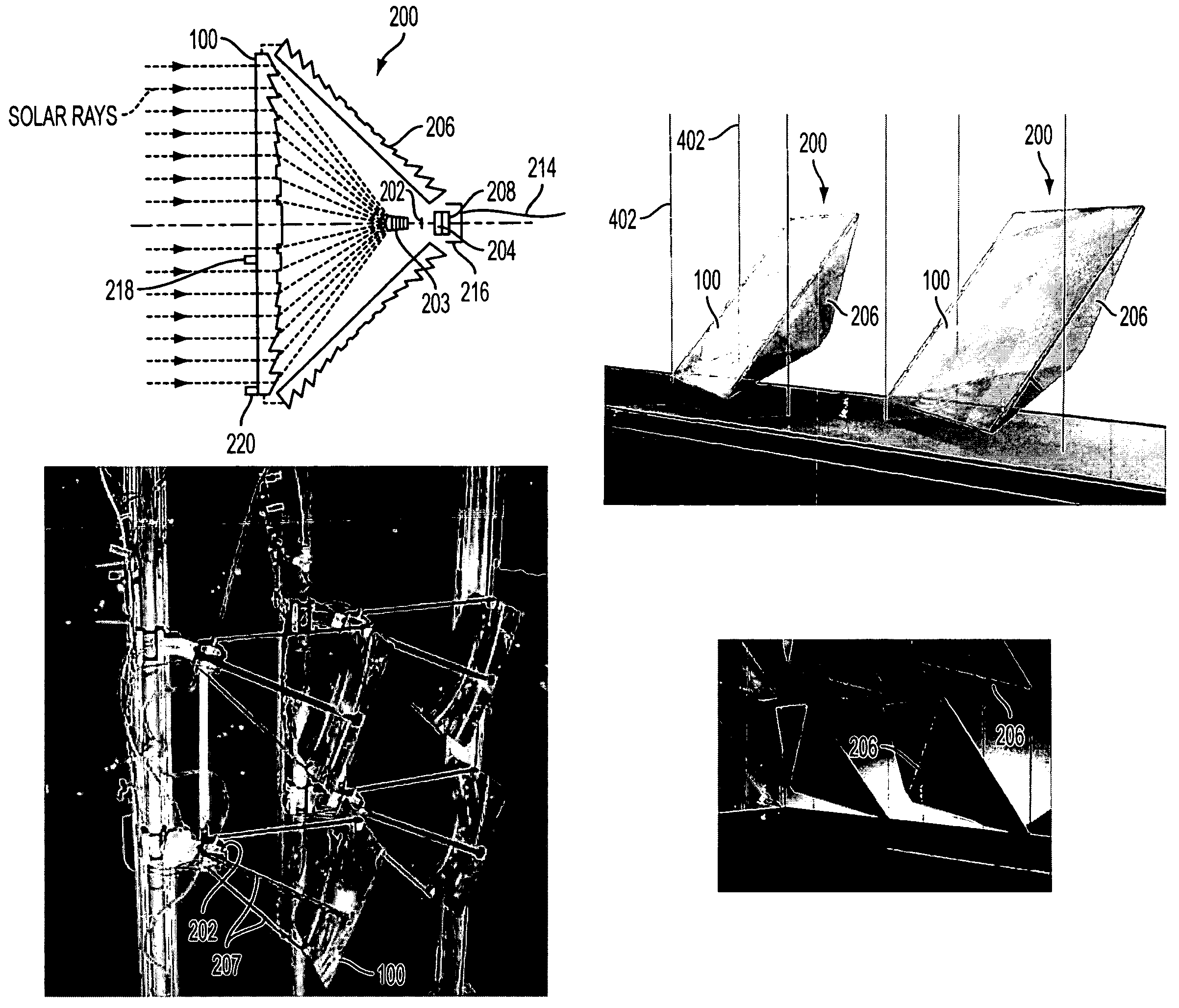
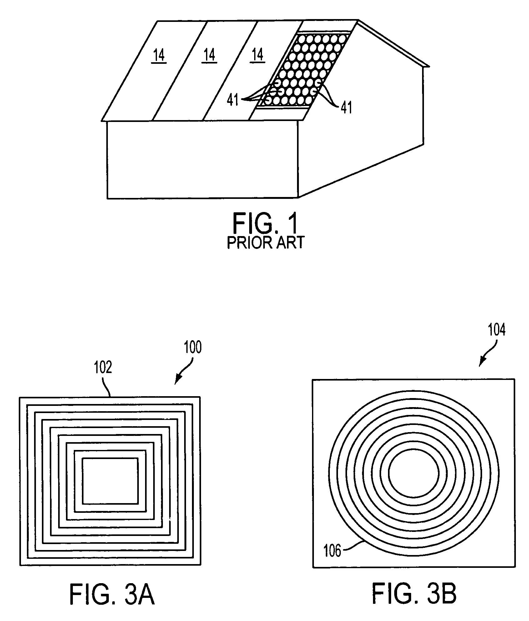
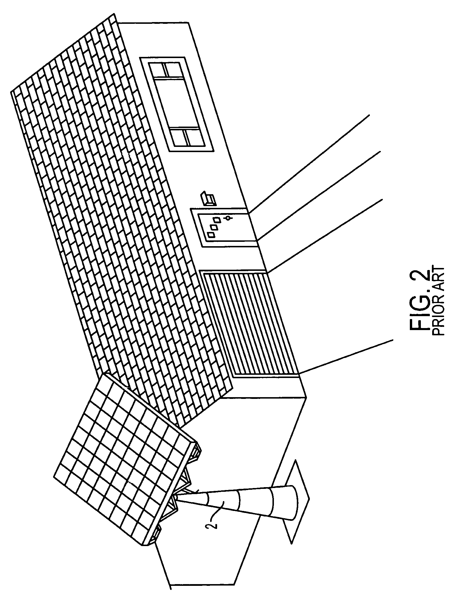
[0035]The present inventors have discovered that by taking a different approach to the flat plate and stand alone technologies, a superior solar power generation system could be achieved. While the ‘flat plate’ PV system is relatively expensive and inefficient to overcome the impediment of long cost pay-back periods, a system of the preferred embodiments of the present invention focuses on integrating concentrator PV technology into existing structural and environmental systems of buildings, thereby removing the need for large, costly tracking devices. The system of the preferred embodiments of the present invention contains a plurality of miniaturized solar modules, each of which contains a photovoltaic (i.e., solar) cell and a focusing device, such as a lens. The term miniaturized means that the modules are at least an order of magnitude smaller than the stand alone PV concentrator system shown in FIG. 2. The modules are integrated and distributed in a building envelope, preferabl...


PUM


Abstract

A Fresnel lens including a substantially polygonal focusing portion adapted to focus solar radiation to a area having the same geometry as the focusing portion of the lens. Also a solar module including the Fresnel collecting lens and a substantially polygonal photovoltaic cell. The photovoltaic cell is mounted at distance from the Fresnel collecting lens so that the size of the area substantially matches the size of the photovoltaic cell. Also a solar panel having multiple modules within a glazed building envelope system. The solar panel also includes an actuating mechanism within the glazed window envelope system. The actuating mechanism is operatively connected to the plurality of solar modules and is adapted to move the solar modules to track the sun.

Description

[0001]This application claims priority to U.S. Provisional application Ser. No. 60 / 475,002, filed on Jun. 3, 2002, entitled “CONCENTRATING TYPE SOLAR COLLECTION AND DAYLIGHTING SYSTEM WITHIN GLAZED BUILDING ENVELOPES,” which is hereby incorporated by reference in its entirety.FIELD OF THE INVENTION[0002]The present invention is directed generally to the generation of solar power and specifically to a multi-function system for the generation of power using concentrating solar collection.BACKGROUND OF THE INVENTION[0003]Conventional technologies used for the generation of solar power include (1) building-integrated ‘flat-plate’ photovoltaic (PV) solar systems and (2) ‘stand-alone’ concentrating PV systems that are removed from the location of power application. Although these technologies work, widespread adoption of these solar powered systems for general use has been hampered by a number of impediments.[0004]The viability of the flat plate technology is hindered by the large amount ...

Claims


Application Information

Patent Timeline
Patent Type & Authority Patents(United States)
IPC IPC(8): G02B3/08F24J2/08F24J2/54F24S23/30F24S50/20H01L31/042H01L31/052
CPCF24J2/085F24J2/542G02B3/08H01L31/0543H02S20/00Y02B10/10Y02E10/43Y02E10/47Y02E10/52Y02B10/20H02S40/22H02S20/23F24S23/31F24S30/452
Inventor DYSON, ANNA H.JENSEN, MICHAEL K.BORTON, DAVID N.
Owner RENESSELAER POLYTECHNIC INST
Why Eureka
Try Eureka