Self-arresting rope belay device

Active Publication Date: 2011-03-31
ZEDEL CORP
View PDF5 Cites 33 Cited by
  • Summary
  • Abstract
  • Description
  • Claims
  • Application Information

AI Technical Summary

Benefits of technology

[0013]There is therefore a need for a rope belay device allowing the user to easily find a braking position enabling progression at a continuous desired speed.
[0014]To satisfy this need, a self-arresting rope belay device is provided comprising a cam arranged to clamp the rope when the rope is under tension, and a lever arranged to act on the cam to progressively release the rope by manual action on the lever. The lever acts on th

Problems solved by technology

This results in the user progressing by jerks, always seeking the rig

Method used


Image

  • Self-arresting rope belay device
  • Self-arresting rope belay device
  • Self-arresting rope belay device

Examples


Embodiment Construction

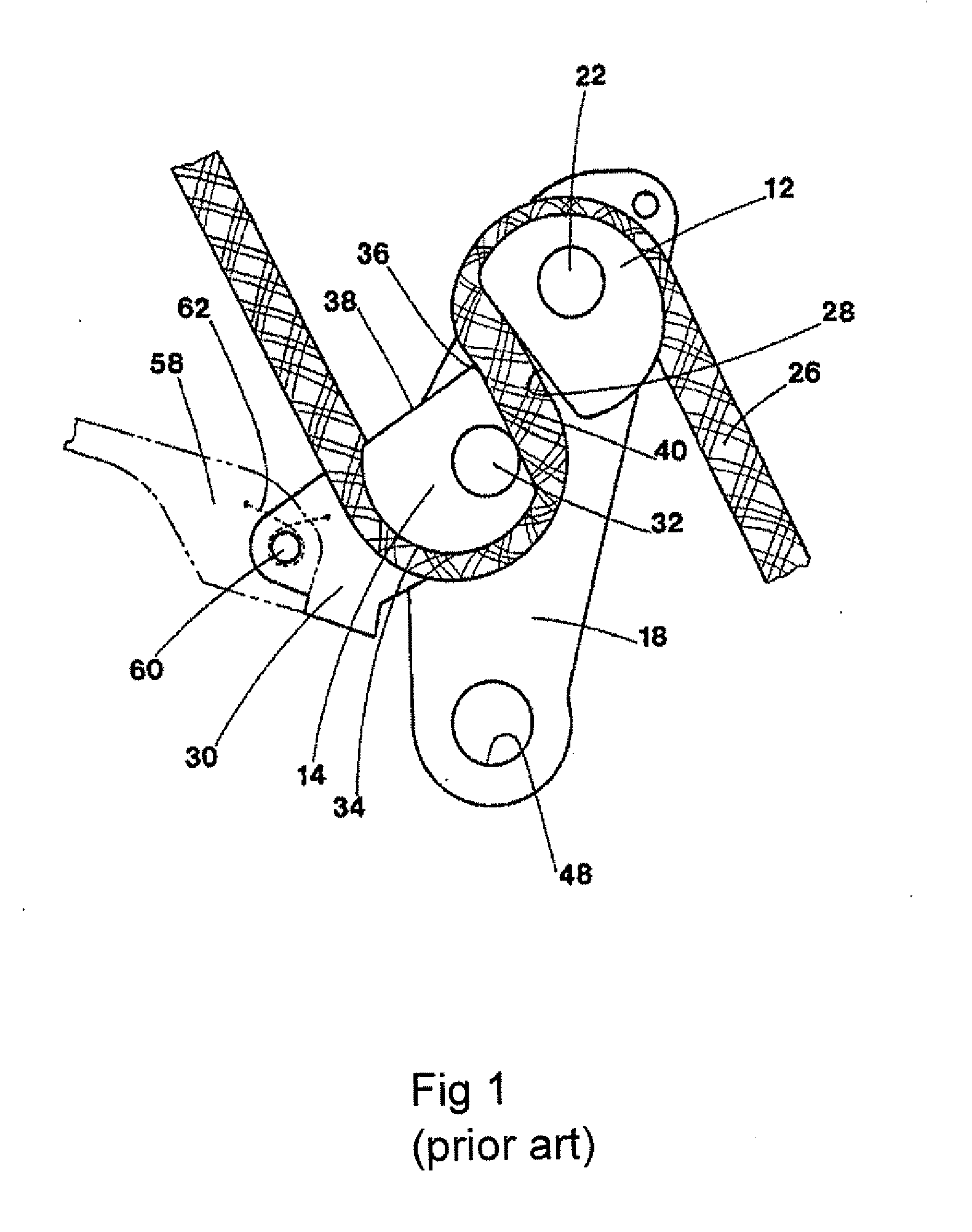
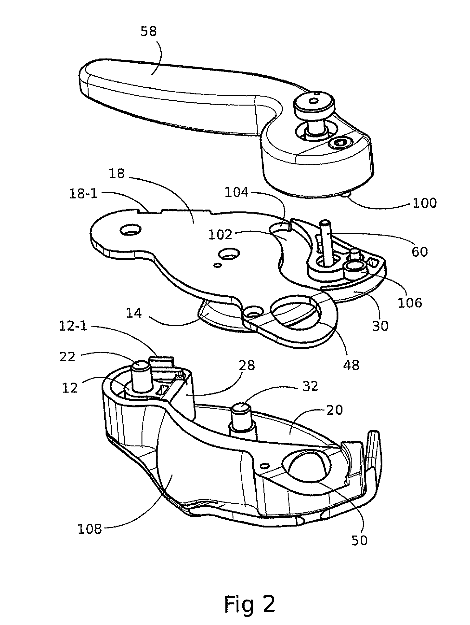
[0022]FIG. 2 represents an exploded perspective view of an embodiment of a belay device offering an accurate control of the running speed of the rope. Elements having similar functions as those of the conventional device of FIG. 1 are shown, and they are designated by the same reference numbers, even if they sometimes have different shapes.

[0023]Flange-plate 18 acting as a reference part for assembling the other component parts is shown. Cam 14 and plate 30 form a single part articulated around pivot pin 32. This single part will hereafter be designated by ‘cam 14’.

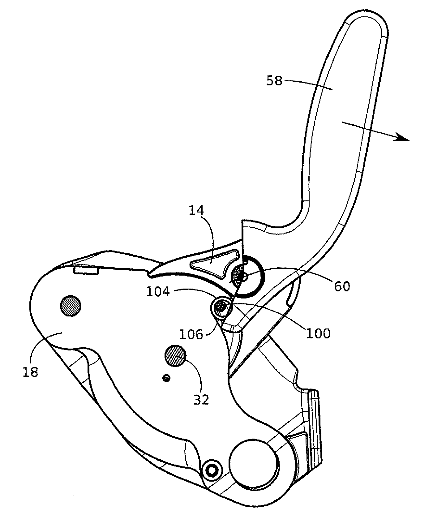
[0024]Lever 58, articulated on cam 14 by means of pivot pin 60, is represented in the rest position, folded back to follow the overall profile of the device.

[0025]To enable accurate control of the running speed of the rope, the base of lever 58, on the side opposite a part forming a handle, is provided with a stud 100 parallel to pivot pin 60. In the represented rest position of the lever, stud 100 is situated on the oppo...


PUM


Abstract

The invention relates to a self-arresting rope belay device comprising a cam arranged to clamp the rope when the rope is under tension, and a lever arranged to act on the cam to progressively release the rope by manual action on the lever. The lever acts on the cam respectively with a geared-down effect in an initial part of its release travel, and with a direct effect in a final part of its travel. This results in the relative movement of the cam with respect to the lever being smaller in the initial part of the travel than in the final part, which enables accurate adjustment of the braking effort and of the running speed of the rope in the initial part of travel of the lever.

Description

BACKGROUND OF THE INVENTION[0001]The invention relates to a self-arresting belay device for a rope, able to act as descender or to belay a climber. Such a device is designed to clamp the rope automatically as soon as the rope is under tension. If the user wants to let the rope run free, he has to perform manual operation on a lever.STATE OF THE ART[0002]FIG. 1 partially represents a conventional self-arresting device in situation, as described in European Patent EP0398819. The device comprises a pair of pulleys 12, 14 housed between two parallel flange-plates, one 18 of which, hereafter called base flange-plate, is represented. The first pulley 12 is fixedly mounted on base flange-plate 18 by means of a securing element 22. Pulley 12 is equipped with a circular top sector having a guide groove for guiding rope 26, and with a braking surface 28 situated facing the second pulley 14. Braking surface 28 is substantially flat.[0003]Second pulley 14 is secured to a support plate 30 mounte...

Claims


Application Information

Patent Timeline
IPC IPC(8): A62B1/14F16D63/00
CPCA62B1/14
Inventor CHAUMONTET, MICHAELQUILLARD, CHRISTOPHEMAURICE, ALAINPETZL, PAUL
Owner ZEDEL CORP
Why Eureka
Try Eureka