High-voltage discharge lamp lighting device and lighting fixture

a high-pressure discharge lamp and lighting device technology, which is applied in the direction of electric variable regulation, process and machine control, instruments, etc., can solve the problems of not being able to restart the lamp, increasing the size, cost, weight, etc. of the lighting device of the high-pressure discharge lamp

Inactive Publication Date: 2011-03-31
PANASONIC CORP
View PDF7 Cites 2 Cited by
  • Summary
  • Abstract
  • Description
  • Claims
  • Application Information

AI Technical Summary

Benefits of technology

The present invention has an effect such that lighting of a high-pressure discharge lamp can be maintained even upon occurrence of an instantaneous power failure, an instantaneous voltage drop, and the like.

Problems solved by technology

Thus, once the lamp DL is extinguished, it is not possible to restart (resume lighting) until the temperature and pressure inside the arc tube are decreased (taking 5 to 15 minutes usually).
Therefore, once the lamp DL is extinguished, it takes time to restart the lamp DL even in a case of a power failure of only a short period (for 10 to 20 ms), such as an instantaneous power failure or an instantaneous voltage drop of the alternating current source AC due to a lightening strike, a start of large electric equipment in the neighborhood, a short-circuit accident, and the like.
However, the increase in the capacity of the smoothing capacitor 120 leads to increases in size, costs, weight, and the like of the high-pressure discharge lamp lighting device.
Such increases cannot meet recent market demands for reducing the size, costs, and weight of high-pressure discharge lamp lighting devices.

Method used


Image

  • High-voltage discharge lamp lighting device and lighting fixture
  • High-voltage discharge lamp lighting device and lighting fixture
  • High-voltage discharge lamp lighting device and lighting fixture

Examples


first embodiment

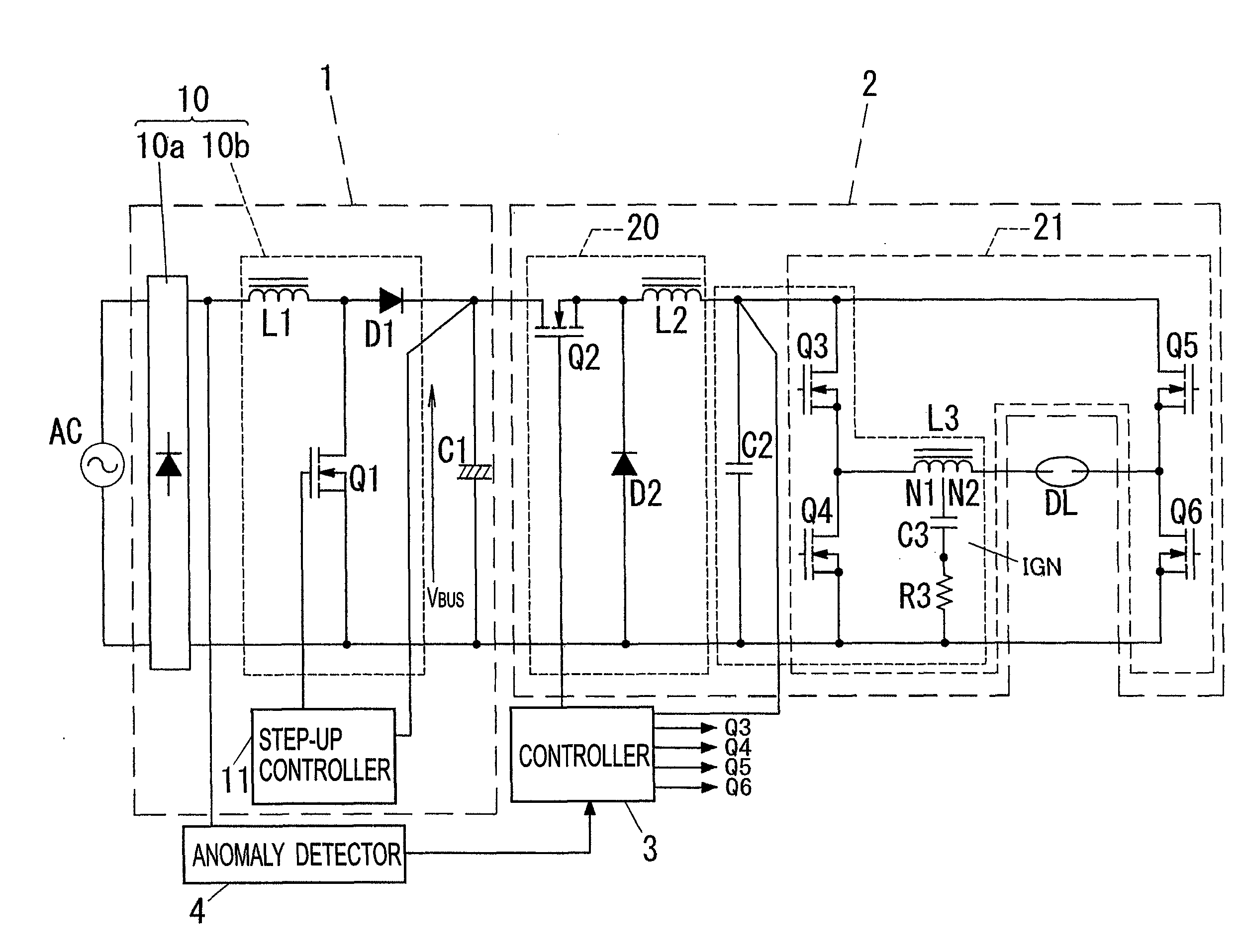
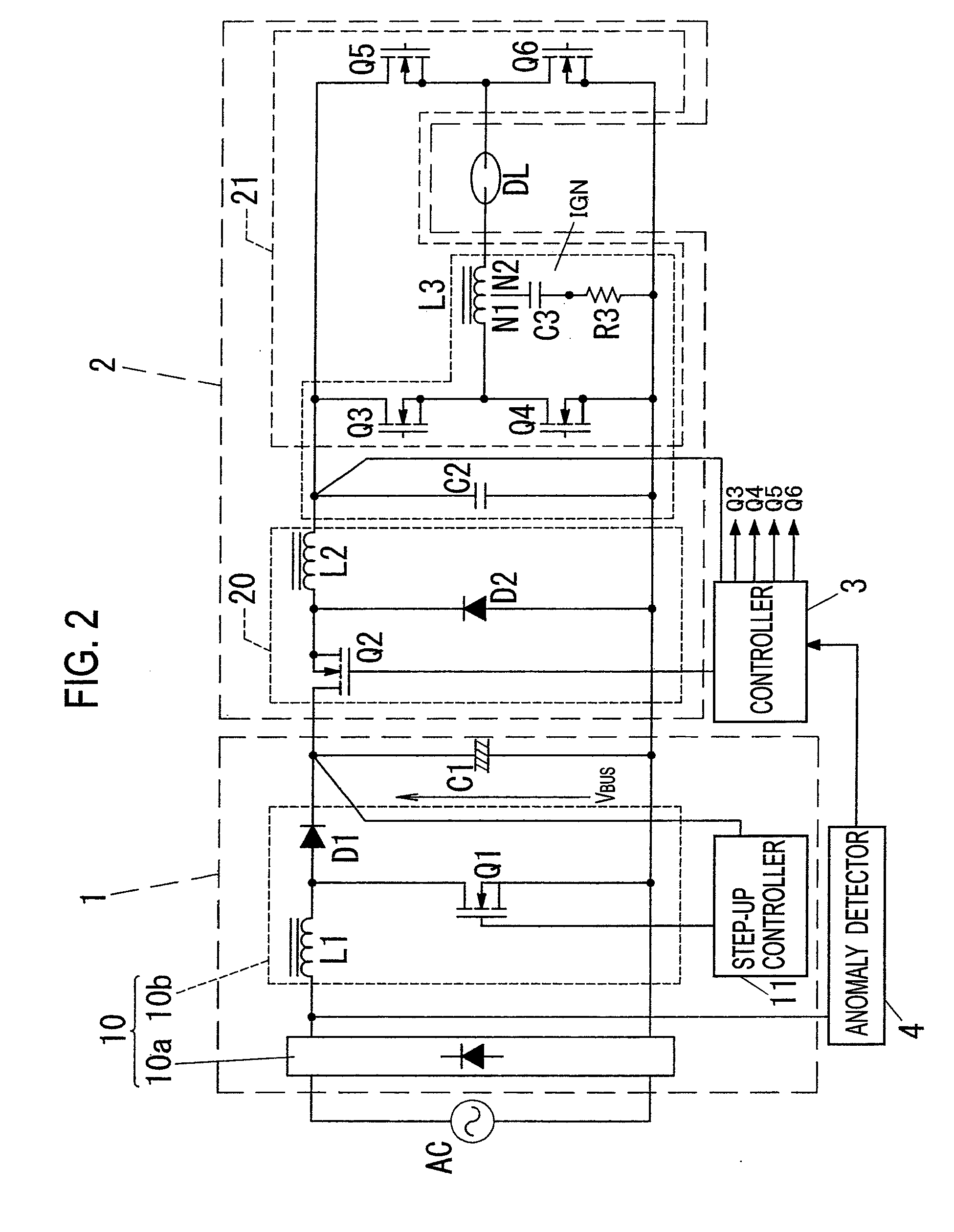
As shown in FIG. 2, a high-pressure discharge lamp lighting device of this embodiment includes a direct current power circuit 1 that converts an alternating current voltage to be supplied form an alternating current power source AC into a direct current voltage, an output unit 2 that converts a direct current outputted from the direct current power circuit 1 into a square wave alternating current whose polarity is inverted at a prescribed frequency and supplies the square wave alternating current to a high-pressure discharge lamp DL, a controller 3 that controls the output unit 2, and an anomaly detector 4 that detects an instantaneous drop in voltage (i.e., an instantaneous power failure or an instantaneous voltage drop) of the alternating current power source AC. Note that a commercial alternating current power having a frequency of 60 Hz and an effective value (a nominal value) of 100 V is assumed as the alternating current power source AC in this embodiment.

The direct current po...

second embodiment

As shown in FIG. 5, a high-pressure discharge lamp lighting device of this embodiment includes a direct current power circuit 1 that converts an alternating current voltage to be supplied form an alternating current power source AC into a direct current voltage, an output unit 2 that converts a direct current outputted from the direct current power circuit 1 into a square wave alternating current whose polarity is inverted at a prescribed frequency and that supplies the square wave alternating current to a high-pressure discharge lamp DL, a controller 3 that controls the output unit 2, and an anomaly detector 4 that detects an instantaneous drop in voltage (i.e., an instantaneous power failure or an instantaneous voltage drop) of the alternating current power source AC.

Here, the direct current power circuit 1 is similar to the one in the first embodiment whereas the output unit 2, the controller 3, and the anomaly detector 4 are different from those in the first embodiment. For this...

third embodiment

A high-pressure discharge lamp lighting device of this embodiment is different from the second embodiment in an operation of the controller 3, but other features are the same as the second embodiment. Accordingly, illustration and description of such similar configurations will be omitted herein.

A controller 3 of this embodiment is different from the second embodiment in an operation in the lighting maintained mode. However, operations in the normal lighting mode and in a starting mode are similar to those in the second embodiment and description thereof will be omitted.

Specifically, the controller 3 of this embodiment executes the positive current supply control in the lighting maintained mode and causes the output unit 2 to supply the current having the polarity thus fixed to positive (the fixed polarity current) to a high-pressure discharge lamp DL. That is, the controller 3 of the second embodiment continues the positive current supply control without switching to the negative c...


PUM


Abstract

A device includes a direct current power circuit configured to convert an alternating current voltage from an alternating current power source into a direct current voltage, an output unit configured to convert a direct current from the direct current power circuit into a square wave alternating current whose polarity is inverted at a prescribed frequency and to supply the square wave alternating current to a high-pressure discharge lamp, a controller, and an anomaly detector configured to detect an instantaneous voltage drop of the alternating current power source. When the anomaly detector detects the instantaneous voltage drop, the controller switches from a normal lighting mode of controlling the output unit to supply the high-pressure discharge lamp with a square wave alternating current to a lighting maintained mode of controlling the output unit to supply the high-pressure discharge lamp with a square wave alternating current having a lower frequency than the square wave alternating current in the normal lighting mode. In this way, it is possible to maintain lighting of the high-pressure discharge lamp even upon occurrence of an instantaneous power failure, an instantaneous voltage drop, and the like.

Description

TECHNICAL FIELDThe present invention relates to a lighting device for a high-pressure discharge lamp and a lighting fixture using the same.BACKGROUND ARTA discharge lamp lighting device (a high-pressure discharge lamp lighting device) has heretofore been proposed which is used for lighting a high-pressure discharge lamp (also referred to as a high-intensity discharge lamp or a HID lamp) such as a metal halide lamp or a high-pressure mercury lamp.As shown in FIG. 1, a high-pressure discharge lamp lighting device of this type includes a rectifier 100 such as a diode bridge that performs full-wave rectification of an alternating electric current supplied from an alternating current power source AC, a step-up chopper circuit 110 that steps up an output voltage from the rectifier 100 to a prescribed value, a smoothing capacitor 120 that smoothes an output voltage from the step-up chopper circuit 110, a step-down chopper circuit 130 that steps down the output voltage from the step-up chop...

Claims


Application Information

Patent Timeline
Patent Type & Authority Applications(United States)
IPC IPC(8): H05B41/36
CPCH05B41/2888Y02B20/202H05B41/2923Y02B20/00
Inventor KUMAGAI, JUNKOMATSU, NAOKI
Owner PANASONIC CORP
Why Eureka
Try Eureka