
Electronic Magnification Device

a technology of electronic magnifiers and magnification devices, which is applied in the field of magnification devices, can solve the problems of insufficient lighting for existing magnifiers, limited lighting for desktop electronic magnifiers, and difficulty in reading books, etc., and achieves the effect of improving lighting arrangement and resolution

Active Publication Date: 2011-03-31
FREEDOM SCI
View PDF39 Cites 50 Cited by
  • Summary
  • Abstract
  • Description
  • Claims
  • Application Information

AI Technical Summary

Benefits of technology

[0009]An advantage provided by the magnifier of the present disclosure is the ability accommodate wider fields of view and higher resolutions via an improved lighting arrangement.
[0011]The disclosed magnifier camera provides yet another advantage by providing two independent mounting arms for the monitor and associated camera.
[0013]Another advantage is achieved by removably securing the monitor via a mounting bracket to thereby permit the monitor to be easily replaced and / or repaired.

Problems solved by technology

People with impaired vision have difficulty reading books, perceiving small objects, or seeing fine detail.
Currently available desktop electronic magnifiers, such as Trulaske, have a number of limitations.
One, limitation is that existing magnifiers do not provide sufficient lighting for cameras having larger fields of view.
Another drawback is that with existing magnifiers there is interference between the camera and monitor.
This results in movement of the camera, which is problematic as the camera must regain focus and be reset to the selected magnification level.
This interrupts viewing and results in periods of blurriness.
Still yet another drawback is that existing magnifiers use dedicated monitors, often with integrated and specialized controls.
This prevents the magnifier from being used with conventional displays and further makes repair and / or maintenance problematic.

Method used


Image

  • Electronic Magnification Device
  • Electronic Magnification Device
  • Electronic Magnification Device

Examples


Embodiment Construction

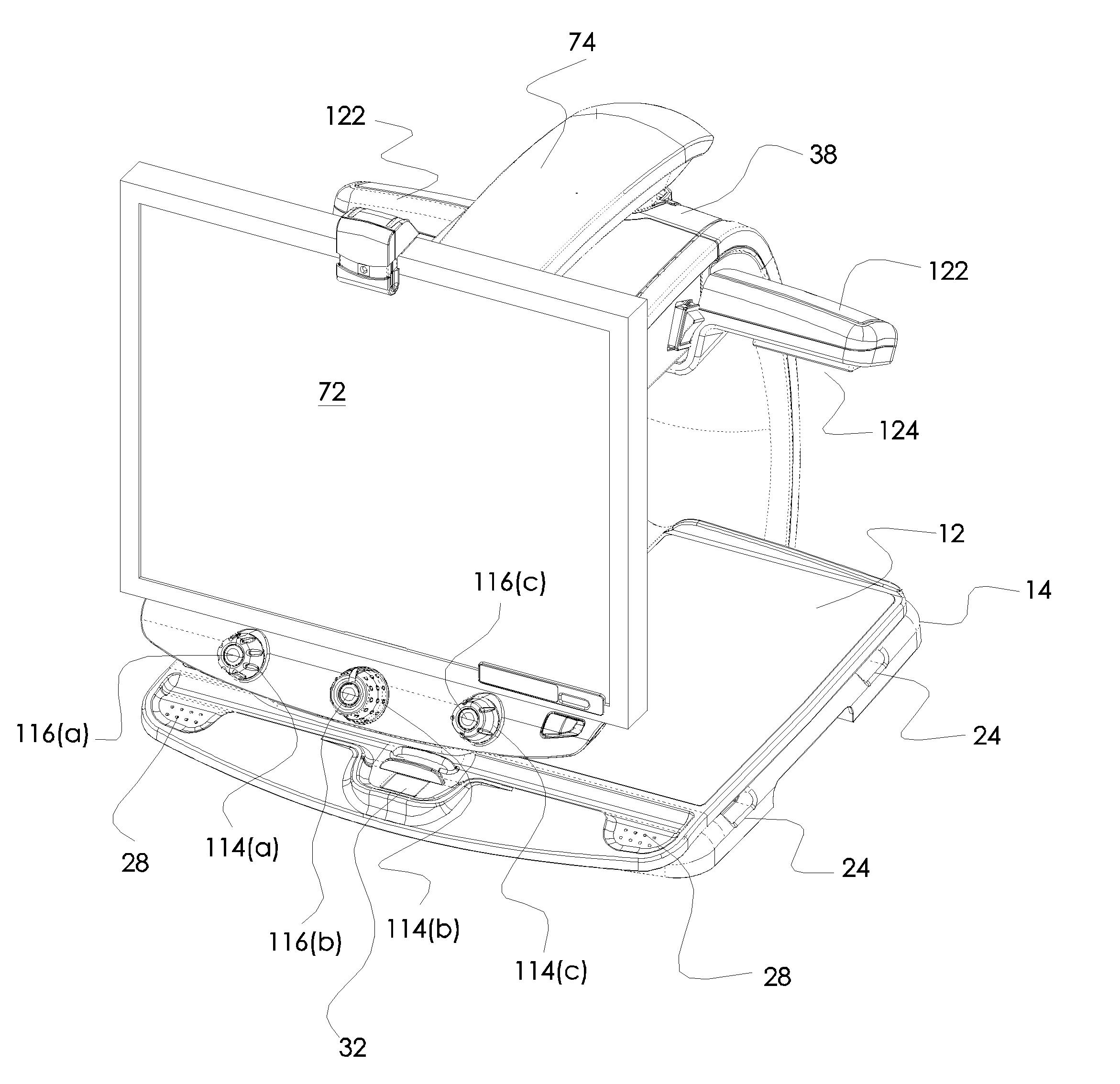
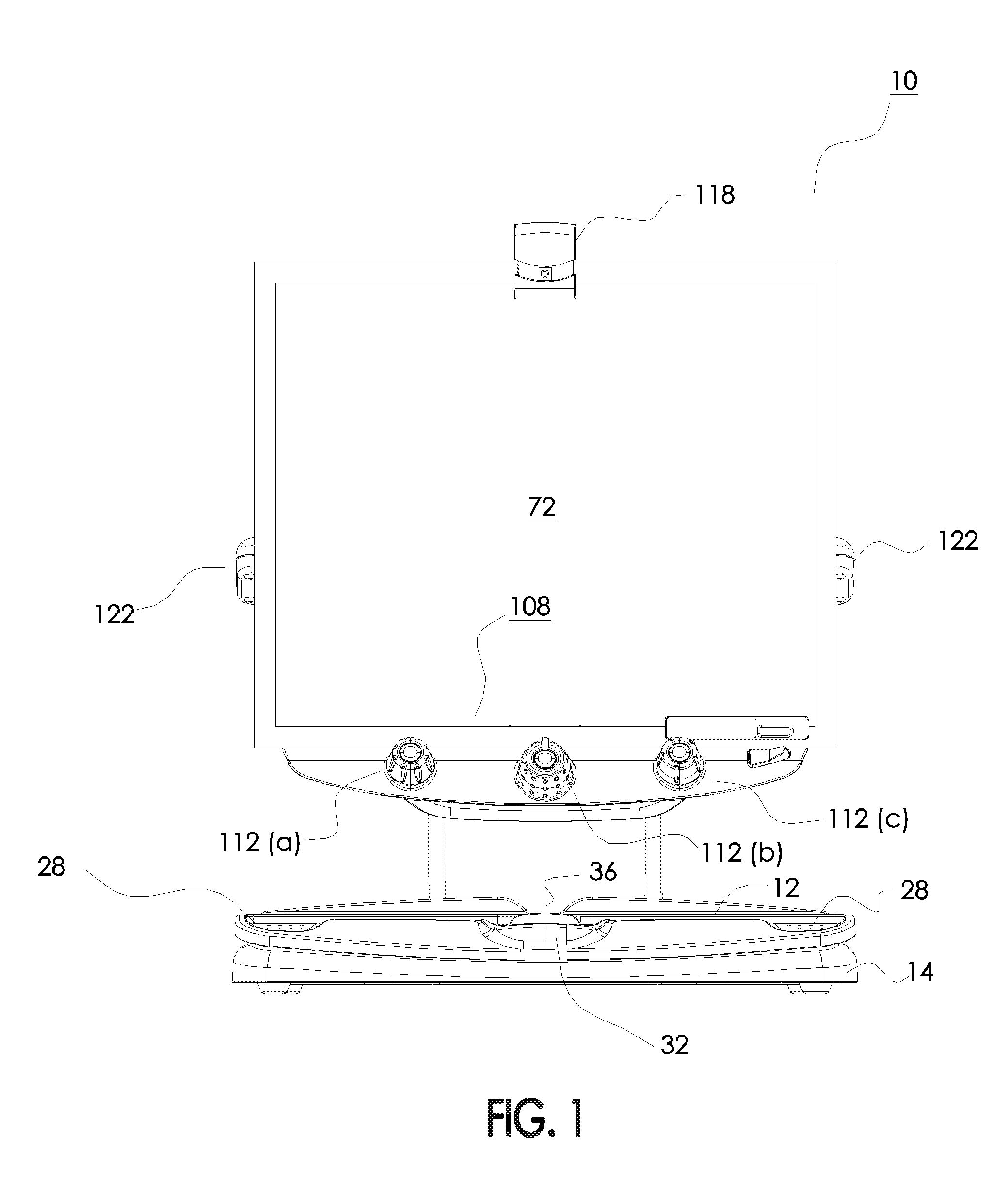
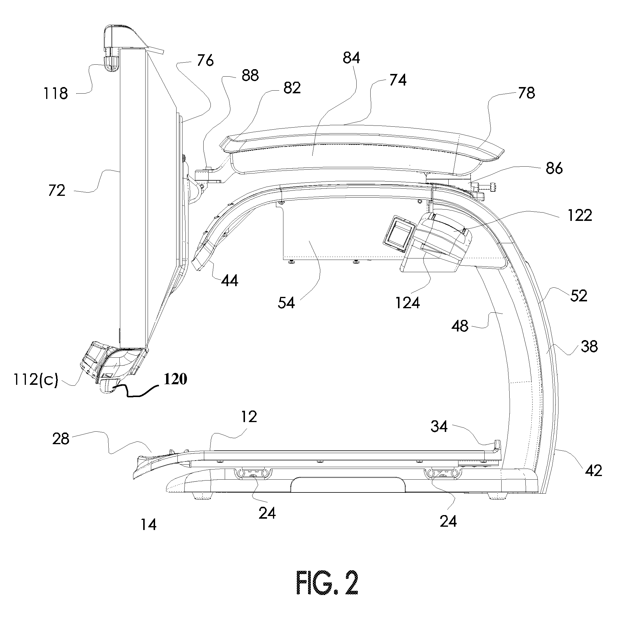
[0030]This disclosure relates to a magnification device for use by blind and / or low vision individuals. The device includes an X-Y table upon which an item to be magnified can be placed. A stationary camera arm and a pivotal monitor arm are oriented over the X-Y table. The monitor arm includes a video monitor pivotally mounted at its distal end. The camera arm also includes a laterally disposed lighting arm. A series of controls are provided along a lower edge of the monitor via a mounting bracket. The various details of the present disclosure, and the manner in which they interrelate, will be described in greater detail hereinafter.

[0031]Device 10 includes an X-Y table 12 that is adjustably mounted to an underlying base 14. Both table 12 and base 14 are defined by forward and rearward edges (16 and 18, respectively) and a pair of side edges 22. Rubber or elastic feet may be positioned on the bottom surface of the base to avoid marring the supporting surface. Two pairs of channels a...


PUM


Abstract

Disclosed is a magnification device for use by blind and / or low vision individuals. The device includes an X-Y table upon which an item to be magnified can be placed. A stationary camera arm and a pivotal monitor arm are oriented over the X-Y table. The monitor arm includes a video monitor pivotally mounted at its distal end. The camera arm also includes two laterally disposed lighting arms. A series of controls are provided along a lower edge of the monitor via a mounting bracket.

Description

RELATED APPLICATION DATA[0001]This application claims priority to co-pending utility application Ser. No. 11 / 379,327 filed on Apr. 19, 2006 and entitled “Desktop Electronic Magnifier.” This application further claims priority to provisional application Ser. No. 60 / 766,783, filed on Feb. 10, 2006. The contents of both these applications are fully incorporated herein for all purposes.BACKGROUND OF THE INVENTION[0002]1. Field of the Invention[0003]This invention relates to a magnification device. More particularly, the invention relates to an adjustable desktop electronic magnifier.[0004]2. Description of the Background Art[0005]People with impaired vision have difficulty reading books, perceiving small objects, or seeing fine detail. Magnifying glasses have long been used to enable the perception of small details which may otherwise be below the unaided resolution of an individual. Desktop electronic magnifiers, sometimes referred to as closed circuit television devices (cctv), have n...

Claims


Application Information

Patent Timeline
IPC IPC(8): H04N7/18
CPCH04N2201/0081H04N2201/0089G03B17/48H04N1/00535H04N1/195H04N2201/043G02B27/026H04N2201/0436G03B27/323H04N5/2251H04N5/23293G06F1/1607G09B21/008H04N1/19594H04N5/2252H04N23/50H04N23/51
Inventor GOLDENBERG, MICHAELDAVIS, BRADLEY S.HAMILTON, LEERODRIGUEZ, CARLOSMURPHYTUNKIS, WALDEMAR
Owner FREEDOM SCI
Learn More