Label producing apparatus

a technology of labeling and producing equipment, which is applied in the direction of typewriters, printing, other printing equipment, etc., can solve the problems of reducing the operability of the guide member, the feeding guide part being unable to stably guide the width direction of the print-receiving tape, and the significant load on the environmen

Active Publication Date: 2011-03-31
BROTHER KOGYO KK
View PDF14 Cites 18 Cited by
  • Summary
  • Abstract
  • Description
  • Claims
  • Application Information

AI Technical Summary

Benefits of technology

[0013]It is therefore a first object of the present disclosure to provide a label producing apparatus capable of reliably guiding a print-receiving tape even when the roll width or outer diameter changes to a different value.
[0014]It is a second object of the present disclosure to provide a label producing apparatus capable of supporting a roll of an arbitrary width.
[0015]It is a third object of the present disclosure to provide a label producing apparatus that makes it possible for a user to easily advance and retreat a guide member, even in a case where the roll outer diameter is large.

Problems solved by technology

Nevertheless, in such a case, since the guide member guides the width direction of the print-receiving tape while in contact with the end face of the roll, the space in which the user is to catch and hold his or her finger between the guide member and roll is difficult to secure when the outer diameter of the roll is large, for example, bringing rise to problems such as a decrease in guide member operability.
Nevertheless, in the range from the feed-out position to the curvature position, the feeding path of the print-receiving tape changes according to the change in value of the roll outer diameter as described above, resulting in the possibility that the feeding guide part will not be able to stably guide the width direction of the print-receiving tape.
In such a case, however, the guide member is generally made of resin, resulting in a significant load on the environment.

Method used


Image

  • Label producing apparatus
  • Label producing apparatus
  • Label producing apparatus

Examples


Embodiment Construction

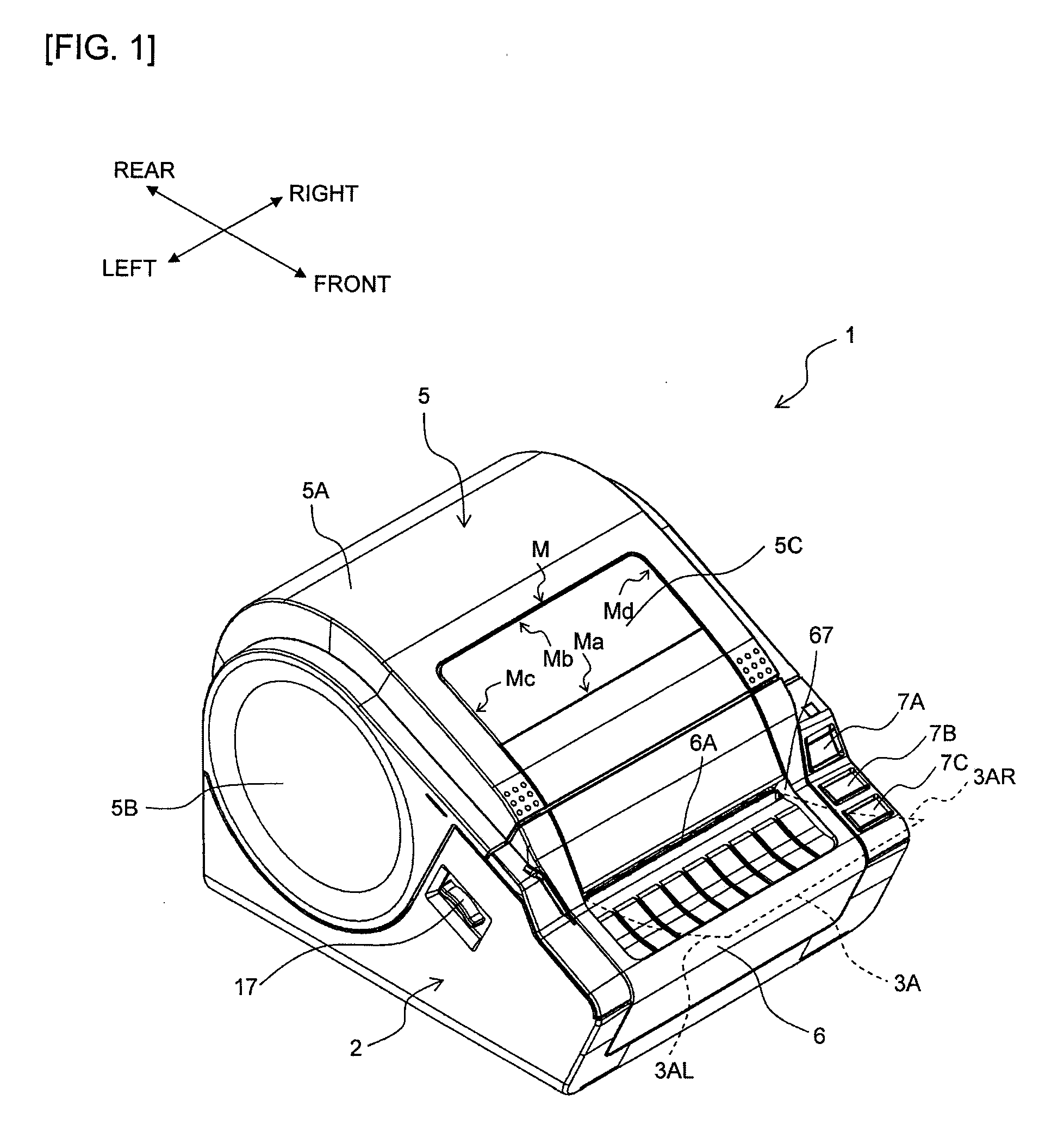
[0063]The following describes an embodiment of the present disclosure with reference to accompanying drawings. First, the outer appearance of a label producing apparatus 1 of the embodiment as viewed from above from the front will be described with reference to FIG. 1. Note that the front, rear, left, and right directions in the following descriptions refer to the directions suitably indicated by arrows in each figure, such as FIG. 1.

[0064]In FIG. 1, the label producing apparatus 1 is provided with a housing 2 comprising a front panel 6, and an upper cover 5. The housing 2 and the upper cover 5 are made of resin. The upper cover 5 comprises an upper cover main body 5A and left and right cover members 5B that are substantially circular in shape. The left and right cover members 5B are secured to the left and right of the upper cover main body 5A by screws, etc. The upper cover main body 5A is rotatably connected to the housing 2 on the rear end part so that the upper cover 5 can be o...


PUM


Abstract

The disclosure discloses a label producing apparatus comprising: a roll housing part that houses a roll winding a print-receiving tape into a roll shape; a feeding roller that feeds out and transports said print-receiving tape from said roll housed in said roll housing part; a printing device that prints desired print on said print-receiving tape fed out from said roll by the feeding of said feeding roller; and a guide device that guides said print-receiving tape fed out from said roll housed in said roll housing part; wherein: said guide device comprises either a first guide part capable of guiding said roll according to roll diameters of different sizes, or a second guide part capable of guiding said roll according to roll widths of different sizes.

Description

CROSS-REFERENCE TO RELATED APPLICATION[0001]The present application claims priority from Japanese Patent Application No. 2009-226174, which was filed on Sep. 30, 2009, the disclosure of which is incorporated herein by reference in its entirety.BACKGROUND[0002]1. Field[0003]The present disclosure relates to a label producing apparatus that produces printed labels by printing desired print on a print-receiving tape.[0004]2. Description of the Related Art[0005]Various label producing apparatuses are known which produce printed labels by printing desired print on a print-receiving tape. Such a label producing apparatus houses a roll around which the print-receiving tape is wound into a roll shape in a roll housing part, feeds out the print-receiving tape from the roll by a feeding device, and prints predetermined print on the print-receiving tape by a printing device. The print-receiving tape on which printing has thus been performed is then discharged outside the housing and, in such a...

Claims


Application Information

Patent Timeline
Patent Type & Authority Applications(United States)
IPC IPC(8): B41J15/02
CPCB41J3/4075B41J15/046B41J15/042B41J11/0025
Inventor KASUGAI, ATSUSHISEO, KEIJI
Owner BROTHER KOGYO KK
Why Eureka
Try Eureka