Double-Grip Golf Putter

Inactive Publication Date: 2011-03-31
DEZALIA SR NORMAN E
View PDF10 Cites 1 Cited by
  • Summary
  • Abstract
  • Description
  • Claims
  • Application Information

AI Technical Summary

Benefits of technology

[0010]It is a more specific object to provide a double-grip putter that places the golfer's hands,

Problems solved by technology

Many golfers experience difficulty in making accurate putts.
This improves the putting accuracy for a small minority of golfers, and is not a perfect solution.
However, because one hand is wrapped around the other hand, the player's hands are not identically positioned.
Also, many golfers have found this grip technique to be a difficult one to learn.
The center member prev

Method used


Image

  • Double-Grip Golf Putter
  • Double-Grip Golf Putter
  • Double-Grip Golf Putter

Examples


Embodiment Construction

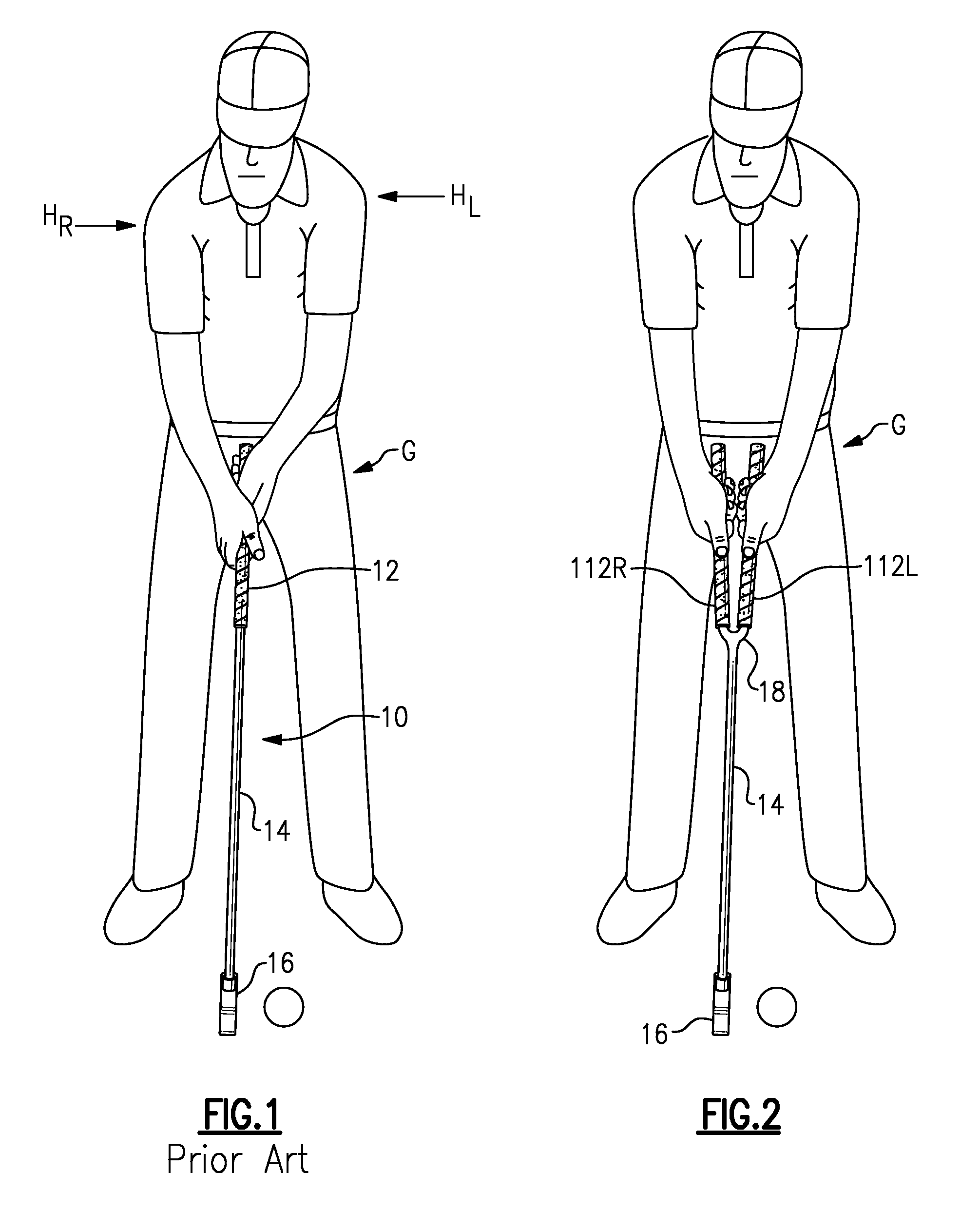
[0020]With reference to the Drawing, and initially to FIG. 1, a golfer G is shown holding a conventional putter 10 having a conventional single grip 12 at the upper end of a putter shaft 14, and with a putter head 16 at the lower end of the shaft. Here, the golfer G is shown in a right-hand putting position, standing with the club head 16 to the golfer's right of the ball. The golfer G has his hands on the club's grip 12, with the left hand above and the right hand further down on the grip. With this gripping technique, the golfer's forearms are angled out from the shaft of the putter, and the golfer's elbows are bent. More significantly, with the right hand further down the grip of the club, the golfer's posture has his right shoulder at a level HR that is somewhat below the level HL of his left shoulder, as indicated by arrows in FIG. 1. This unevenness of stance makes it difficult for many golfers to control the putter so that the ball consistently travels as intended towards the...


PUM


Abstract

A dual grip putter has a pair of grip members rising from the upper end of the putter shaft, forming a Vee at an angle of about fifteen to eighteen degrees, with an open space between the two grip members. Upper ends of the grip members are spaced about 2½ inches apart. This arrangement positions the golfer's hands so that his or her forearms are aligned with the upper arms, with elbows generally straight, and so that the shoulders are both at an even height.

Description

BACKGROUND OF THE INVENTION[0001]This invention relates to golfing equipment, and is more specifically directed to golf putter, i.e., golf clubs that are intended for use on a putting green to strike a golf ball precisely and propel it towards the golf hole on the green. The invention is more particularly concerned with a golf putter with an improved handle or grip portion at the upper end of the putter shaft, designed to position the golfer in a natural, even, and symmetrical stance, and to afford greater control and accuracy in putting the ball towards the hole.[0002]The traditional single-grip putter has the grip extending straight at the upper end of the shaft and along the axis of the shaft. The lower end of the shaft may have a gooseneck just above the hosel of the putter head, or the shaft may be straight as it enters the hosel, but the upper part of the shaft is straight and defines the axis of the putter. The grip has a wrap of natural or synthetic leather, or a cover of a ...

Claims


Application Information

Patent Timeline
IPC IPC(8): A63B53/14
CPCA63B53/007A63B53/10A63B59/0055A63B59/004A63B53/14A63B60/20A63B60/34A63B60/00
Inventor DEZALIA, SR., NORMAN E.
Owner DEZALIA SR NORMAN E
Why Eureka
Try Eureka