
Semi-automated cap securing apparatus

a technology of automatic attachment and cap, which is applied in the direction of caps, rotating screw stopper insertion, application, etc., can solve the problems that the current available mechanized devices cannot be easily used, consistently, etc., and achieve the effect of convenient proper engagement of the cap securing apparatus and quick replacemen

Inactive Publication Date: 2012-11-01
KINEX CAPPERS
View PDF14 Cites 6 Cited by
  • Summary
  • Abstract
  • Description
  • Claims
  • Application Information

AI Technical Summary

Benefits of technology

[0005]Another object of the present invention is to provide a cap securing apparatus which facilitates easy, quick, reliable and accurate securing or unsecuring of a cap to the threaded opening of a container, by moving a plurality of rotatable wheels laterally or radially inward toward a portion of a centrally located cap so that the rotatable wheels can frictionally engage with a lateral surface of the cap and induce a desired rotation, i.e., tightening or untightening, of the cap which sufficiently rotates the cap relative to the threaded opening of the container.
[0006]A further object of the present invention is to provide substantially simultaneously activated drive mechanism and a cap engagement mechanism which cooperate with one another for securing / unsecuring the cap with the threaded opening of the container and, once this is achieved, the cap engagement mechanism facilitates movement of the rotatable wheels, from contact with the lateral surface of the cap, so that the container can be removed and replaced with a new container having a new cap to be either secured thereto or removed therefrom.
[0007]Yet another object of the present invention is to provide a pressurized air or fluid actuator, which is preferably pneumatically or hydraulically actuated, that is arranged to actuate simultaneously at least one (1), more preferably at least two (2) and most preferably three (3) or four (4), movable or pivotally mounted (pivotable) arms, which are each coupled with a vertically movable constrictor plate that controls movement of the pivotable arms and thereby facilitates both engagement of the rotatable wheels, accommodated at a remote free end of each of the pivotable arms, with the cap to be secured / unsecured, as well as disengagement and release of the rotatable wheels, supported by the remote free end of each of the pivotable arms, from the secured / unsecured cap once the cap is sufficiently rotated, relative to the container, by the cap securing apparatus.
[0009]A still further additional object of the present invention is to provide a cap securing apparatus in which the rotatable wheel, accommodated by the free end of each one of the movable or pivotable arms, can be readily replaced as necessary or desired so as to facilitate the cap securing apparatus properly engaging with the desired cap to be secured to a desired container.
[0010]It is to be appreciated that there are several ways to approach the problem of accurately and repeatably securing or unsecuring caps of various shapes and sizes with respect to containers of various shapes and sizes. A standard line of cap tightening products may excel at torquing / untorquing the caps with the containers, but they will be limited to simple shaped caps and will typically not work with caps which include a nozzle, a spray head, a pump spout, a pump dispenser or any other protruding feature of cap, for example. The cap securing apparatus, according to the present invention, provides an arrangement in which the movable or pivotable arms move essentially radially inwardly toward a cap to be capped / uncapped, but are sufficiently spaced from the cap so as to provide a vertical area above the rotatable wheels which is not breached or entered into by any component(s) or element(s) of the cap securing apparatus.

Problems solved by technology

One drawback with such mechanized devices is that the rotatable head must have an unobstructed axial path from vertically above the cap, so as to permit the rotatable head to receive and engage with the top and / or sides of the cap so as to permit inducing relative rotation thereto.
However, when the cap includes an additional component(s) or feature(s), such as a pump head, a spray head, an irregular shaped top portion, etc., then an unobstructed axial path is not present for securing / unsecuring such cap and thus the currently available mechanized devices cannot be used for easily, consistently and reliably securing / unsecuring the caps to or from the containers.

Method used


Image

  • Semi-automated cap securing apparatus
  • Semi-automated cap securing apparatus
  • Semi-automated cap securing apparatus

Examples


Embodiment Construction

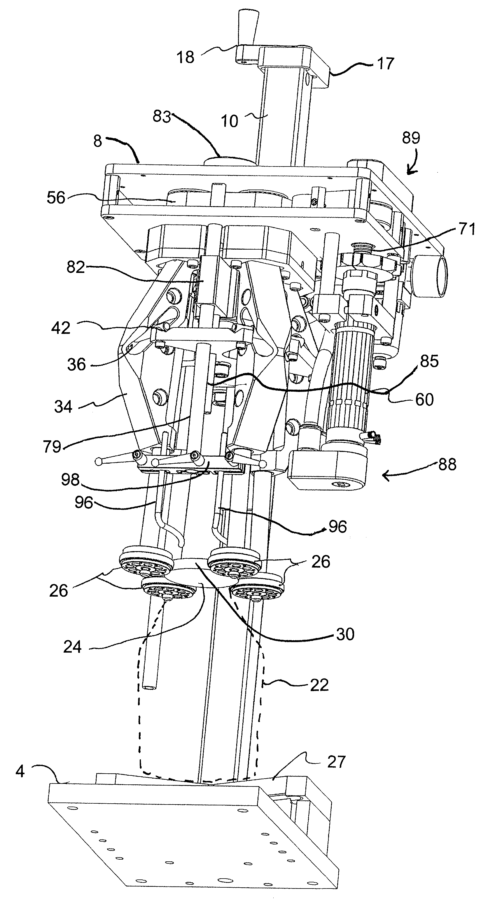
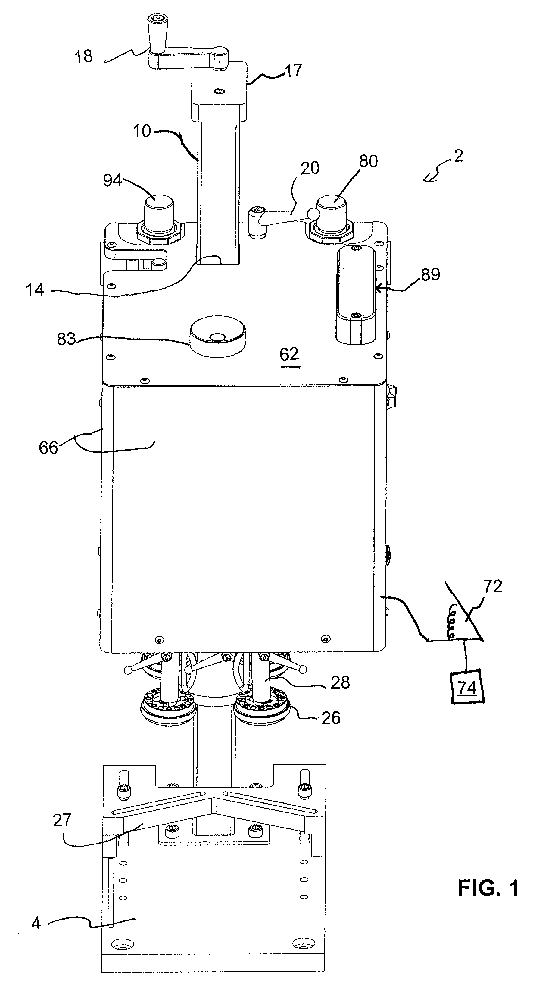
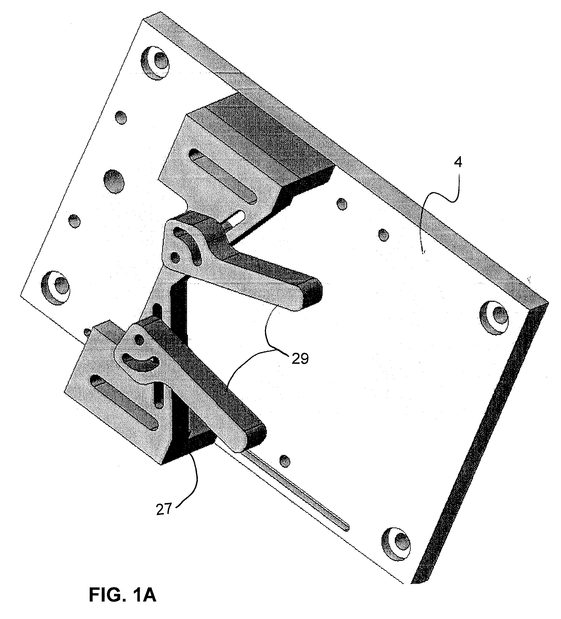
[0034]With reference now to FIGS. 1-3 of the drawings, a detail description concerning the various components of the cap securing apparatus, according to the present invention, will now be briefly discussed. As can be seen generally in those Figures, for example, the cap securing apparatus 2 generally comprises a support base 4 for supporting the cap securing apparatus 2 on a desired surface, for example, such as a table, an assembly platform or a workbench. A top surface of the support base 4 also supports a desired container 22 (see FIG. 7, for example) to be capped / uncapped, which will be discussed below in further detail. A first end of a post assembly 6 is permanently secured to the support base 4 while an adjustable main support 8 (see FIG. 3, for example), of the cap securing apparatus 2, is adjustably supported by and movable along the post-assembly 6 so as to facilitate adjustment of the relative spacing between the main support 8 and the support base 4.

[0035]The post-assem...


PUM


Abstract

A cap securing apparatus for rotating a cap relative to a container. The cap securing apparatus comprises a support base supporting a main support, the main support supporting a plurality of arms, and each of the plurality of arms supporting a rotatable wheel adjacent a remote free end thereof. A drive mechanism supplies drive to at least one of the rotatable wheels, supported by the plurality of arms, for inducing rotation thereof. A cap engagement mechanism moves the wheels from a disengaged first position, in which the wheels are spaced from the cap to be one of capped or uncapped with respect to the container, into an engaged second position in which the wheels engage with the cap for inducing rotation of the cap and one of capping the cap to the container and uncapping the cap from the container.

Description

FIELD OF THE INVENTION[0001]The present invention relates to a pump, a collar, a cover or a cap securing apparatus for easily, consistently and reliably capping / uncapping a desired pump, collar, cover or cap (all of which are hereinafter collectively referred to as a “cap”) to the threaded opening of a desired container.BACKGROUND OF THE INVENTION[0002]A variety of mechanized devices are currently available in the prior art for rapid torquing and securing or untorquing and unsecuring a threaded cap to or from a threaded opening of a container. One such device generally comprises a single rotatable head with an internal cavity which receives, surrounds and frictionally engages with the cap, via an axially downward directed motion of the head from above the cap. Once the rotatable head sufficiently frictionally engages with the cap, the rotatable head is then activated to apply sufficient torque to rotate the cap, relative to the container, and sufficiently cap or uncap the cap to the...

Claims


Application Information

Patent Timeline
IPC IPC(8): B67B3/20
CPCB67B3/2006B67B7/182B67B3/2073B67B3/206
Inventor ARGERIOU, JAMESQUINLAN, LAWRENCE J.
Owner KINEX CAPPERS
Learn More