Compact Tool Box with Ratchet Driving Function

a tool box and driving function technology, applied in the field of compact tool boxes with ratcheting driving function, can solve the problems of limited force applied by users, substantially cubic handle bodies that cannot be effectively reduced in width or height, and the combination of tools that are difficult to carry, etc., to facilitate the description of the invention

Active Publication Date: 2011-04-21
HU BOBBY
View PDF8 Cites 18 Cited by
  • Summary
  • Abstract
  • Description
  • Claims
  • Application Information

AI Technical Summary

Benefits of technology

[0028]All figures are drawn for ease of explanation of the basic teachings of the present invention only; the extensions of the figures with respect to number, position, relationship, and dimensions of the parts to form the preferred embodiments will be explained or will be within the skill of the art after the following teachings of the present invention have been read and understood. Further, the exact dimensions and dimensional proportions to conform to specific force, weight, strength, and similar requirements will likewise be within the skill of the art after the following teachings of the present invention have been read and understood.
[0029]Where used in the various figures of the drawings, the same numerals designate the same or similar parts. Furthermore, when the terms “first”, “second”, “third”, “inner”, “outer”, “side”, “end”, “portion”, “section”, “axial”, “lateral”, “annular”, “spacing”, “clockwise”, “counterclockwise”, and similar terms are used herein, it should be understood that these terms have reference only to the structure shown in the drawings as it would appear to a person viewing the drawings and are utilized only to facilitate describing the invention.

Problems solved by technology

Such a tool handle combination is not easy to carry due to the considerable length of the driving stem.
The objects received in the spaced result in a substantially cubic handle body that can not be effectively reduced in width or height.
However, the force applied by the user is limited, because the width and the height of the handle body are approximately the same.
Namely, rotating the tool handle combination is laborsome.
Furthermore, the repeatedly openable cover can not effectively transmit the force applied by the user.
Further, the cover is liable to slide relative to the base or to deform when the user intends to apply large torque, leading to loss of kinetic energy during transmission.
As a result, the user often feels difficulty during operation.
In worse conditions, the handle body could be damaged by the large torque.
However, the repeatedly removable cap can not effectively transmit the force applied by the user.
Furthermore, the cover is liable to slide relative to the body or to deform when the user intends to apply large torque, leading to loss of kinetic energy during transmission.
As a result, the user often feels difficulty during operation.
In worse conditions, the body could be damaged by the large torque.
However, the repeatedly pivotable first and second brackets can not effectively transmit the force applied by the user.
Furthermore, the first or second bracket is liable to slide relative to the base or to deform when the user intends to apply large torque, leading to loss of kinetic energy during transmission.
As a result, the user often feels difficulty during operation.
In worse conditions, the base could be damaged by the large torque.
Further, even though the receptacle hole of the first bracket is located adjacent to the side of the base, rotation of the toolbox is not smooth when driving a screw in a limited space such as a corner of a wall, because the user has to repeatedly disengage the screwdriver head from the screw and reengage with the screwdriver with head the screw.
Further, the receptacle hole has differing spacings to the edges of the base, leading to limitation to the use of the toolbox.

Method used


Image

  • Compact Tool Box with Ratchet Driving Function
  • Compact Tool Box with Ratchet Driving Function
  • Compact Tool Box with Ratchet Driving Function

Examples


Embodiment Construction

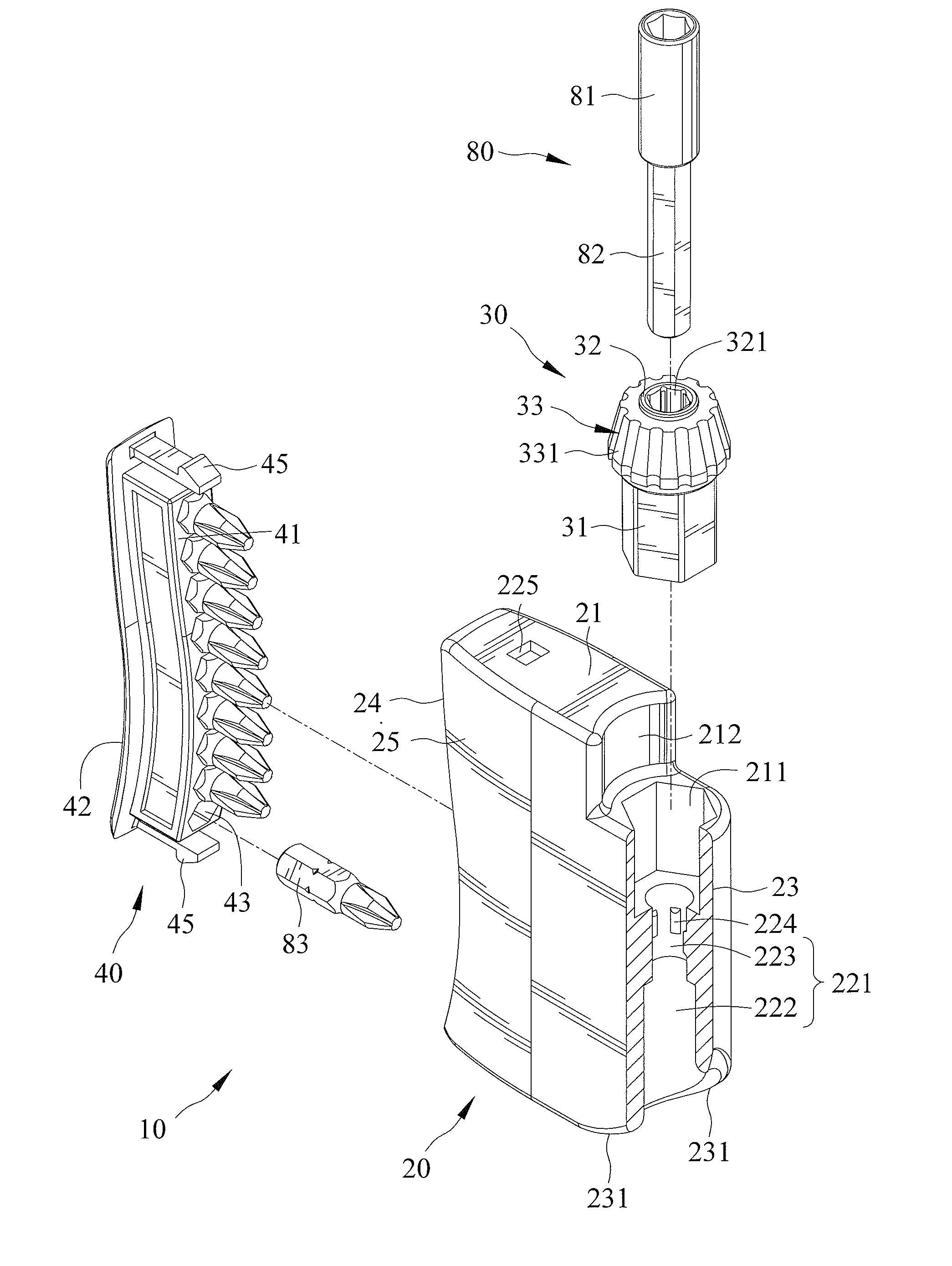
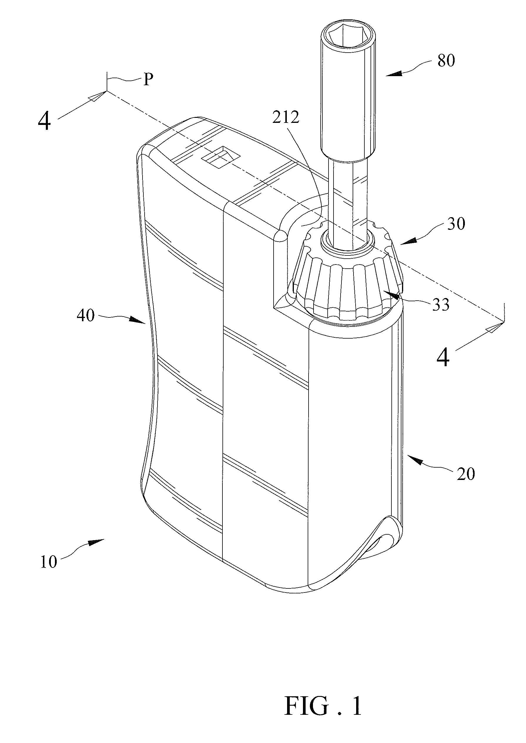
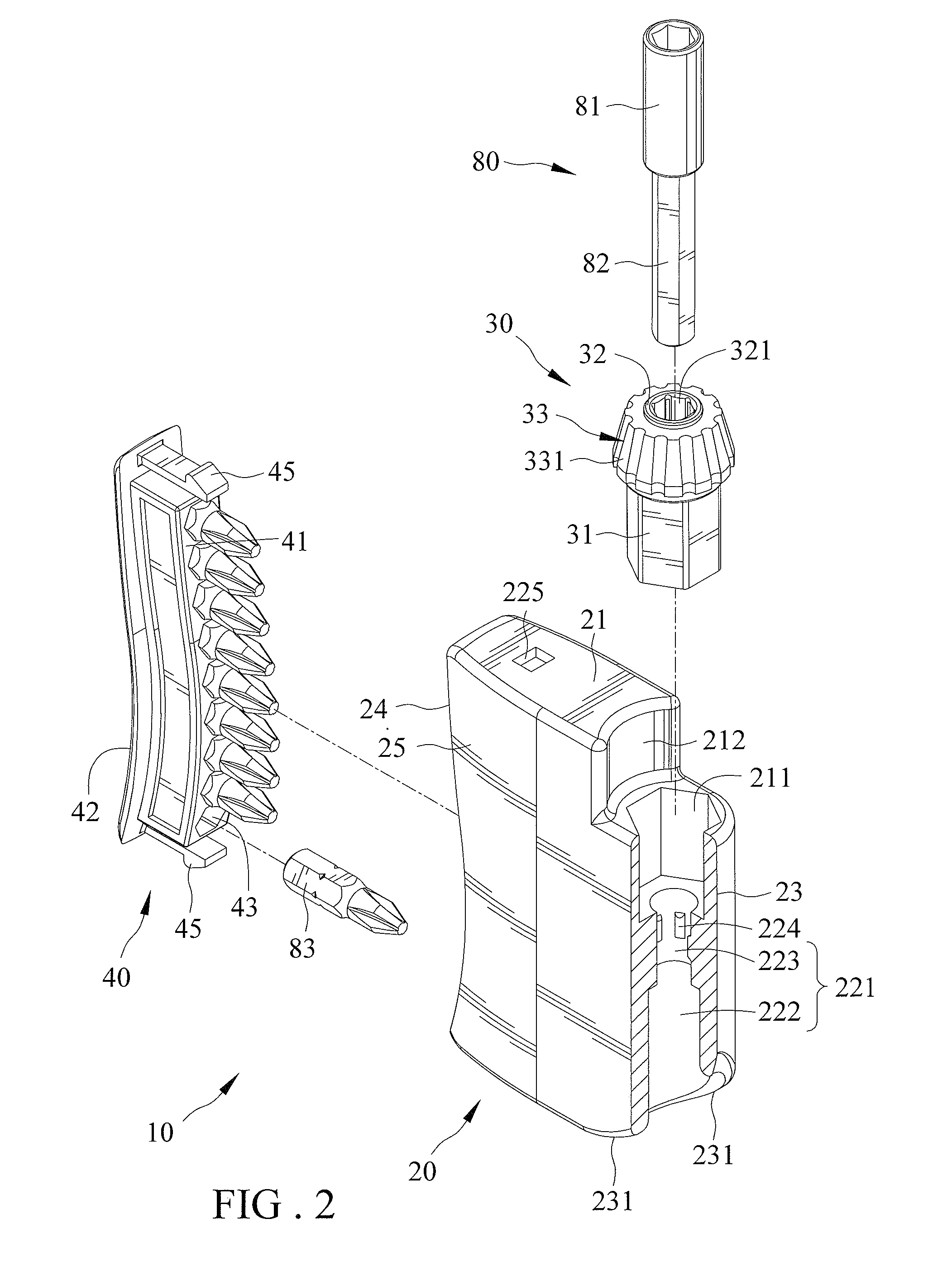
[0030]With reference to FIGS. 1-9, a tool box 10 of a first embodiment according to the preferred teachings of the present invention includes a body 20, a ratcheting mechanism 30, and a rack 40.

[0031]Body 20 is substantially a parallelepiped and includes a front end 21 and a force-receiving portion 22 spaced from front end 21 in a first direction X. Body 20 further includes first and second sides 23 and 24 spaced in a second direction Y perpendicular to first direction X and extending between front end 21 and force-receiving portion 22. Body 20 further includes two lateral walls 25 spaced in a third direction Z perpendicular to first and second directions X and Y and extending between front end 21 and force-receiving portion 22 and between first and second sides 23 and 24. Lateral walls 25, front end 21 and force-receiving portion 22 are integrally formed as a single and inseparable component of the same material.

[0032]A first maximum dimension of body 20 in first direction X betwee...


PUM


Abstract

A tool box includes a body having a front end and a force-receiving portion spaced from the front end. The body further includes first and second sides and two lateral walls. The lateral walls, the front end, and the force-receiving portion are integrally formed as a single and inseparable component of the same material. The front end includes a compartment. A receiving space is defined between the lateral walls and has an opening in the second side or the force-receiving portion. A ratcheting mechanism includes a main body mounted in the body and a ratchet wheel rotatably received in the main body. The ratchet wheel is located in a quarter corner of the body adjacent to the front end and the first side. A driving groove is defined in the ratchet wheel for engaging and driving a shank to rotate. A bit-receiving rack is removably received in the receiving space.

Description

BACKGROUND OF THE INVENTION[0001]The present invention relates to a compact tool box with ratcheting driving function and, more particularly, to a tool box that can be used in a corner of a wall and that is small in size while providing a force-saving driving effect.[0002]U.S. Pat. No. 6,243,902 discloses a tool handle combination including a driving stem mounted to a handle body. The handle body has a base and a cover mounted on top of the base. The cover and the base together define a space for receiving bits, sockets or other tools. Such a tool handle combination is not easy to carry due to the considerable length of the driving stem. The objects received in the spaced result in a substantially cubic handle body that can not be effectively reduced in width or height. A user can apply a force along the longitudinal axis of the driving stem to engage the bit with a workpiece such as a screw. Furthermore, the user can apply a force in a clockwise or counterclockwise direction for ro...

Claims


Application Information

Patent Timeline
Patent Type & Authority Applications(United States)
IPC IPC(8): B25B15/04B25F1/02B25H3/02B25G1/08B25B23/16
CPCB25H3/003B25G1/085
Inventor HU, BOBBY
Owner HU BOBBY
Why Eureka
Try Eureka