Fuel nozzle lip seals

a technology of lip seals and fuel nozzles, which is applied in the direction of fuel injecting pumps, machines/engines, lighting and heating apparatus, etc., can solve the problems of high leakage rate, piston rings, and high leakage performance between passages of fuels with smaller molecules for reliable operation

Inactive Publication Date: 2011-04-21
GENERAL ELECTRIC CO
View PDF8 Cites 32 Cited by
  • Summary
  • Abstract
  • Description
  • Claims
  • Application Information

AI Technical Summary

Benefits of technology

[0005]The present application thus provides a fuel nozzle assembly. The fuel nozzle assembly may inclu...

Problems solved by technology

The more recent use of fuels with smaller molecule sizes also requires exceptionally low leakage performance between passages for reliable operation.
The piston rings, however, may have high leakage rates a...

Method used


Image

  • Fuel nozzle lip seals
  • Fuel nozzle lip seals
  • Fuel nozzle lip seals

Examples


Embodiment Construction

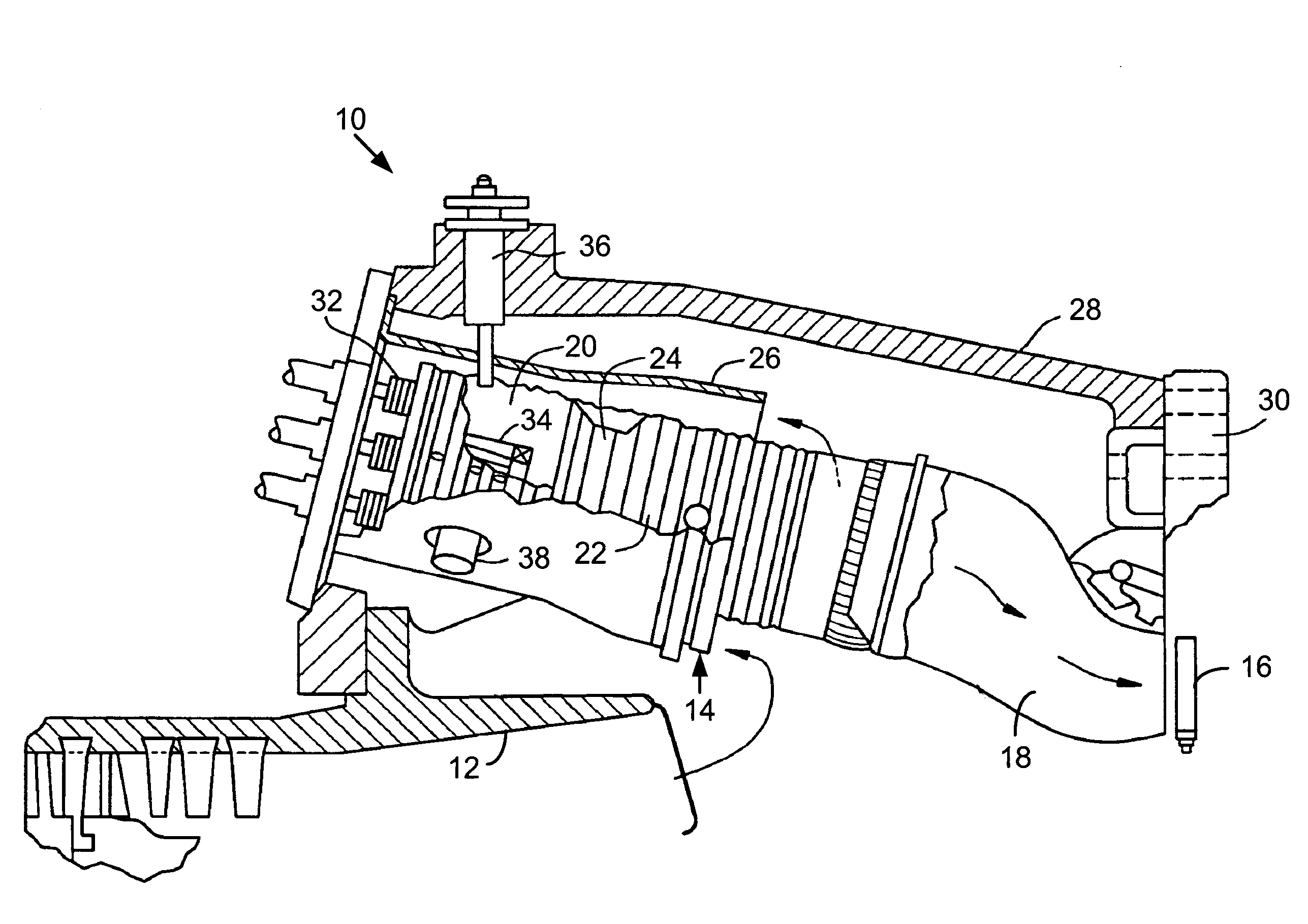
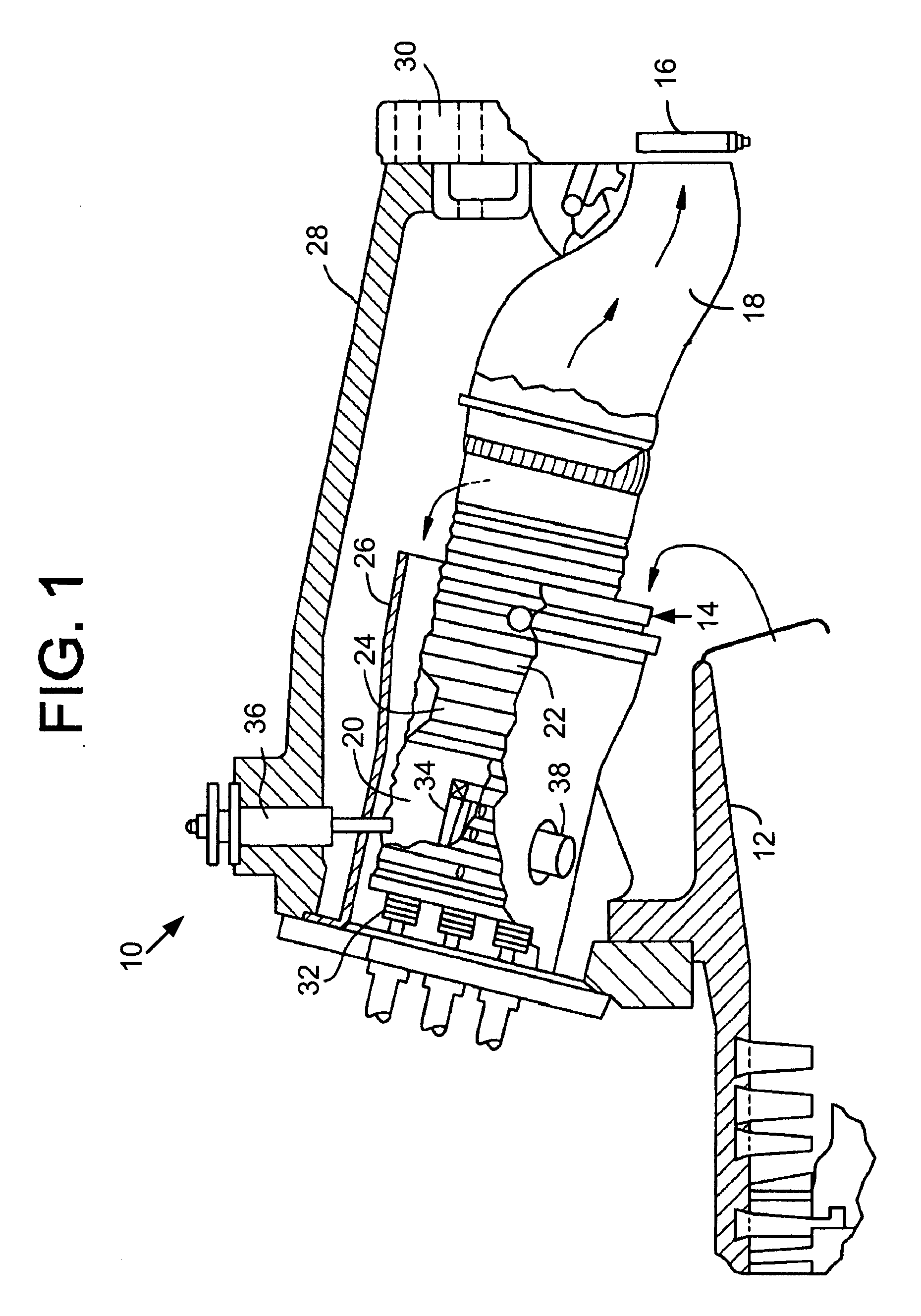
[0014]Referring now to the drawings, in which like numbers refer to like elements throughout the several views, FIG. 1 shows portions of a gas turbine engine 10 with a compressor 12 (also partially shown), a combustor 14, and a turbine section 16 represented here by a single blade. Although not specifically shown, the turbine 16 is connected to the compressor 12 along a common axis. The compressor 12 compresses an incoming flow of air and delivers the air to the combustor 14. The combustor 14 mixes the compressed flow of air with a compressed flow of fuel and ignites the mixture. Although only a single combustor 14 is shown, the gas turbine engine 10 may include any number of combustors 14. The combustors 14 may be located in an annular array about the axis of the gas turbine engine 10,

[0015]The hot combustion gases are in turn delivered to the turbine 16. The hot combustion gases drive the turbine 16 so as to produce mechanical work. The mechanical work produced by the turbine 16 d...


PUM


Abstract

The present application provides a fuel nozzle assembly. The fuel nozzle assembly may include a number of concentric tubes and one or more lip seals positioned between a pair of the concentric tubes.

Description

TECHNICAL FIELD[0001]The present application relates generally to gas turbine engines and more particularly relates to the use of lip seals in combustor nozzles, end covers, and elsewhere.BACKGROUND OF THE INVENTION[0002]Gas turbine combustors generally use a number of fuel nozzles positioned. about an end cover. The fuel nozzles and / or end covers deliver various fluids to the combustion system. Generally, the fluid passages of the fuel nozzles may take the form of concentric tubing. Fluid temperature differences, internal combustion chamber air temperature differences, tubing coefficient of thermal expansion differences, and transient gas turbine operations may contribute to axial thermal strains imposed on the concentric tubing. The more recent use of fuels with smaller molecule sizes also requires exceptionally low leakage performance between passages for reliable operation. Additionally, the fuel nozzles and end covers generally are rigidly attached to the turbine structure. For...

Claims


Application Information

Patent Timeline
IPC IPC(8): F02M61/18
CPCF23R2900/00012F23R3/283
Inventor STOIA, LUCAS JOHNNEGRONI, ALBERTO
Owner GENERAL ELECTRIC CO
Why Eureka
Try Eureka