Spanning tree flooding backbone systems and methods for link state routed networks

a backbone system and link state technology, applied in data switching networks, frequency-division multiplexes, instruments, etc., can solve the problems of bringing the network down, overloading the routing control processor, and wide-spread loss of topology database information, so as to reduce the transmission of messages

Active Publication Date: 2011-04-21
CIENA
View PDF6 Cites 43 Cited by
  • Summary
  • Abstract
  • Description
  • Claims
  • Application Information

AI Technical Summary

Benefits of technology

[0012]In another exemplary embodiment of the present invention, a method of flooding topology messages in a link state routed network includes determining a spanning tree through the link state routed network; designating links on the spanning tree as flooding links; at each node in the link state routed network, communicating node topology status to neighbors; and transmitting messages in the link state routed network only on the flooding links thereby reducing the transmitted messages. The method further includes determining the spanning tree utilizing an administrative weight for each link in the link state routed network. The method further includes repairing the spanning tree responsive to one or more failures such that the spanning tree is not rebuilt with the determining step. The method further includes designating each node in the link state routed network as one of a stub node, a spanning tree node, a multi-link flooding node, a dead-end node, and an isolated node based on a topology of the spanning tree; the stub node connects to only one link of the spanning tree and at least one other link not in the spanning tree; the spanning tree node connects to exactly two links in the spanning tree; the multi-link flooding node connects to two or more links of the spanning tree; the dead end node connects only to one link of the spanning tree; and the isolated node has no links connected to it. The method further includes utilizing one of the stub nodes to repair the spanning tree on one of the at least one other link not in the spanning tree responsive to a failure on a link in the spanning tree. The method further includes at each node in the link state routed network, providing notification to neighboring nodes of the node designation; and responsive to a failure, updating the node designation and notifying the neighboring nodes. The method further includes, responsive to a failure on a link not in the spanning tree, providing only a node status update. The method further includes, responsive to simultaneous failures, arbitrating between two stub nodes to determine which of the two stub nodes repairs the spanning tree.

Problems solved by technology

Unfortunately, congestion in LS protocols due to flooding of control messages (LSAs and PTSEs) has caused many problems in the past.
It can arise for many different reasons and can result in widespread loss of topology database information and overload in flooding of topology database information.
In some instances of network overload, failure and / or congestion, flooding mechanisms can overwhelm routing control processors and bring the network down.
A number of data network outages have been reported by service providers where the recovery of the underlying LS protocols was inadequate.
In such an environment, flooding as originally defined is clearly an impractical and unsustainable method.
A node's control processor (even with multi-core processors) will become easily overwhelmed as failures occur and the time for the network to converge will take 100s of seconds, if not 1000s of seconds, which the customer will find unacceptable.
Many flooding reduction methods have been proposed and implemented, but there are drawbacks to those techniques and so there is still room for improvement.
The problems associated with flooding are the single biggest reason inhibiting networks from scaling.
The key problem with these approaches is that all nodes have to rerun these algorithms after they have received LSAs / TSEs, so the new backbone can take some time to be rebuilt.
The use of “areas” have been found to increase and not reduce the amount of flooding, an informational RFC written by Mikkel Thorup documents some of the harmful effects of using OSPF areas, which include: peculiarities of area routing can result in “funny area routing”; areas are likely to increase information, especially if the number of border routers for a given area is bigger than the degree (number of incident links) for each internal router; simple link-failure can lead to an avalanche of distance changes flooding the network with the use of areas; and the use of “summarization” can lead to unintended infinite loops.
This is very inefficient; it can take hundreds of seconds in a large network where there are 100s of nodes.
This results in the network taking a long time to converge, since all nodes have to first receive the update messages and then run the algorithm.

Method used


Image

  • Spanning tree flooding backbone systems and methods for link state routed networks
  • Spanning tree flooding backbone systems and methods for link state routed networks
  • Spanning tree flooding backbone systems and methods for link state routed networks

Examples


Embodiment Construction

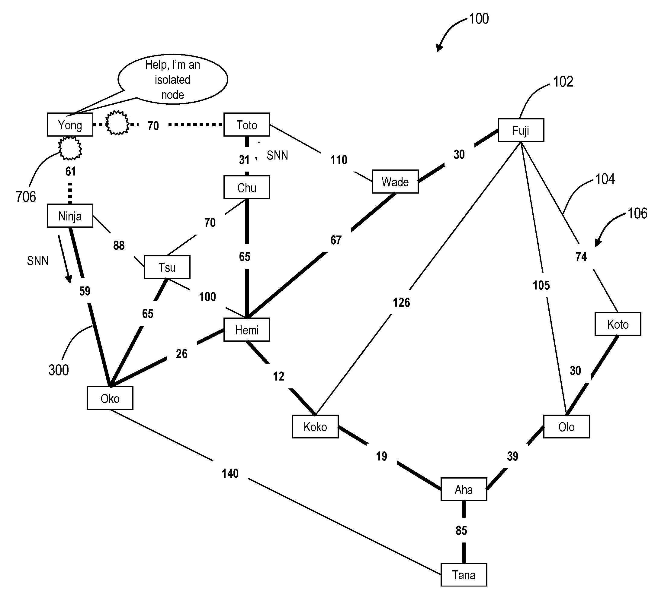
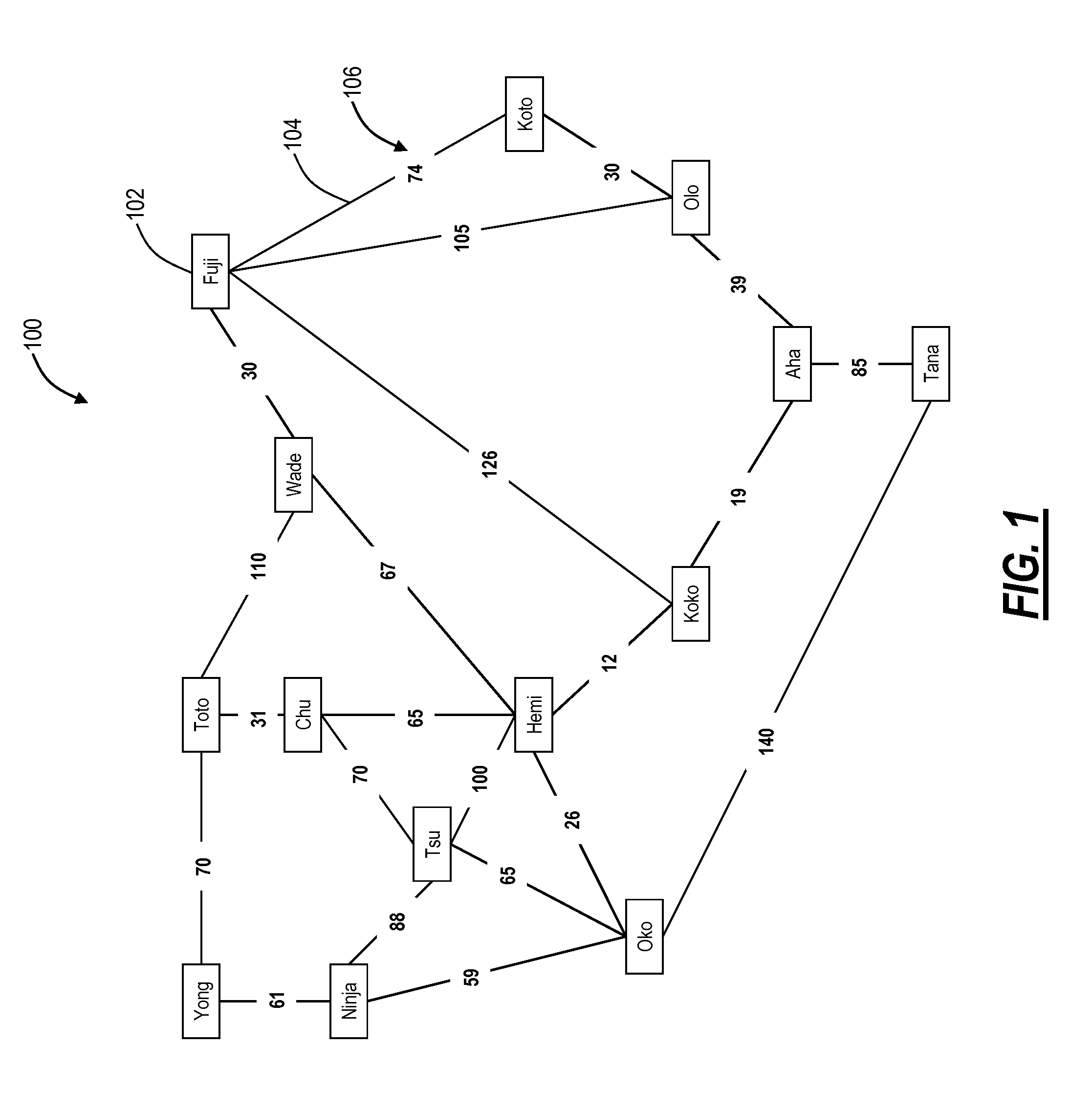
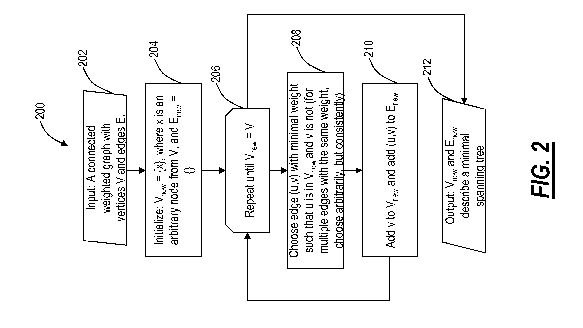
[0024]In various exemplary embodiments, the present invention creates an efficient topology (i.e., a flooding backbone) for distributing topology messages in link state routed networks and efficiently repairing that “flooding backbone” when a failure occurs. The present invention utilizes a simply method of maintaining and reconstructing the topology after a fault has occurred in the network. As described herein, flooding is a robust and simple mechanism to implement but is very inefficient in link state routed networks using protocols such as PNNI and OSPF. Flooding of link state updates entails broadcasting a link state update message in an OSPF network out of all interfaces except the one upon which it was received. If the node generates an LSA due to one of its interfaces, it broadcast the LSA out of all interfaces that are still up and running, and this process is repeated at each node, until all nodes in the topology have receives the update message, which leads to a vast numb...


PUM


Abstract

The present disclosure provides systems and methods for a spanning tree topology used as a “flooding backbone” for control messages on a link state routed network. Specifically, control messages are only broadcast on the flooding backbone thereby significantly reducing message flooding. The present disclosure also provides systems and methods for correctly and efficiently reconfiguring/fixing the spanning tree topology in the event of any spanning tree link failures without re-running the spanning tree protocol.

Description

FIELD OF THE INVENTION[0001]The present invention relates generally to networking systems and methods, and more particularly, to systems and methods for reducing the number of topology messages in link state routed networks when those messages are flooded and efficiently repairing a message broadcast backbone after failures have occurred on links between nodes.BACKGROUND OF THE INVENTION[0002]Link state (LS) routing protocols such as Open Shortest Path First (OSPF), Intermediate system to intermediate system (IS-IS), and Private Network-to-Network Interface (PNNI) (upon which Optical Signaling and Routing Protocol (OSRP) is based) require an accurate view of the network topology (this includes knowledge regarding the presence of nodes and links, their network address, and their state (up / down) as well as the value of all link metrics (e.g., their cost)) in order to calculate optimal routes to a destination node. These LS routing protocols use topology-state update mechanisms to buil...

Claims


Application Information

Patent Timeline
Patent Type & Authority Applications(United States)
IPC IPC(8): H04L12/24H04L12/28
CPCH04L41/0659H04L43/0811H04L45/48H04L45/32H04L45/025
Inventor SMITH, ALEXANDER A.OLTMAN, JOHN K.
Owner CIENA
Why Eureka
Try Eureka