Calculation of downhole pump fillage and control of pump based on said fillage

a technology of pump fillage and calculation method, which is applied in the direction of positive displacement liquid engine, seismology for waterlogging, instruments, etc., can solve the problems of inaccurate determination of pump fillage, difficulty in making a diagnosis of downhole conditions solely on the basis of the shape of the graphical representation, and inability to accurately calculate the fluid production

Active Publication Date: 2011-04-21
WEATHERFORD TECH HLDG LLC
View PDF10 Cites 21 Cited by
  • Summary
  • Abstract
  • Description
  • Claims
  • Application Information

AI Technical Summary

Benefits of technology

[0011]Another embodiment of the present invention provides a system. The system generally includes a pump and a control unit for controlling the pump. The pump typically has a pump barrel, a plunger, a standing valve and a traveling valve. The control unit is typically configured to determine a transfer point of a stroke of the pump, wherein the transfer point occurs during a downstrok

Problems solved by technology

Owing to the diversity of card shapes, however, it can be difficult to make a diagnosis of downhole conditions solely on the basis of the shape of the graphical representation.
Fu

Method used


Image

  • Calculation of downhole pump fillage and control of pump based on said fillage
  • Calculation of downhole pump fillage and control of pump based on said fillage
  • Calculation of downhole pump fillage and control of pump based on said fillage

Examples


Embodiment Construction

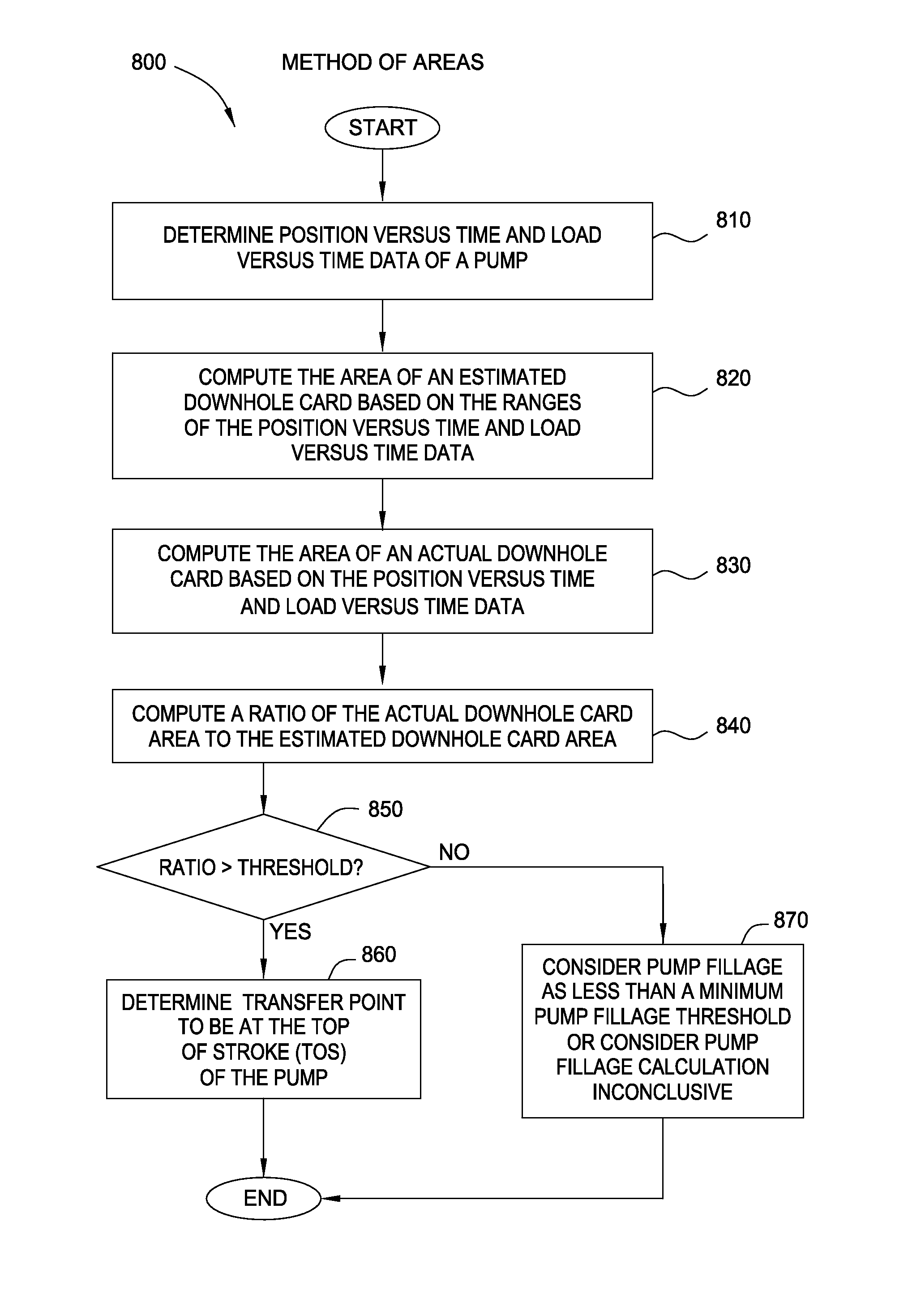
[0022]Embodiments of the present invention provide numerical methods for determining pump fillage using data arrays of pump plunger position with respect to time and / or pump plunger load with respect to time. This may allow well operators to accurately monitor the pump fillage and control the pump accordingly.

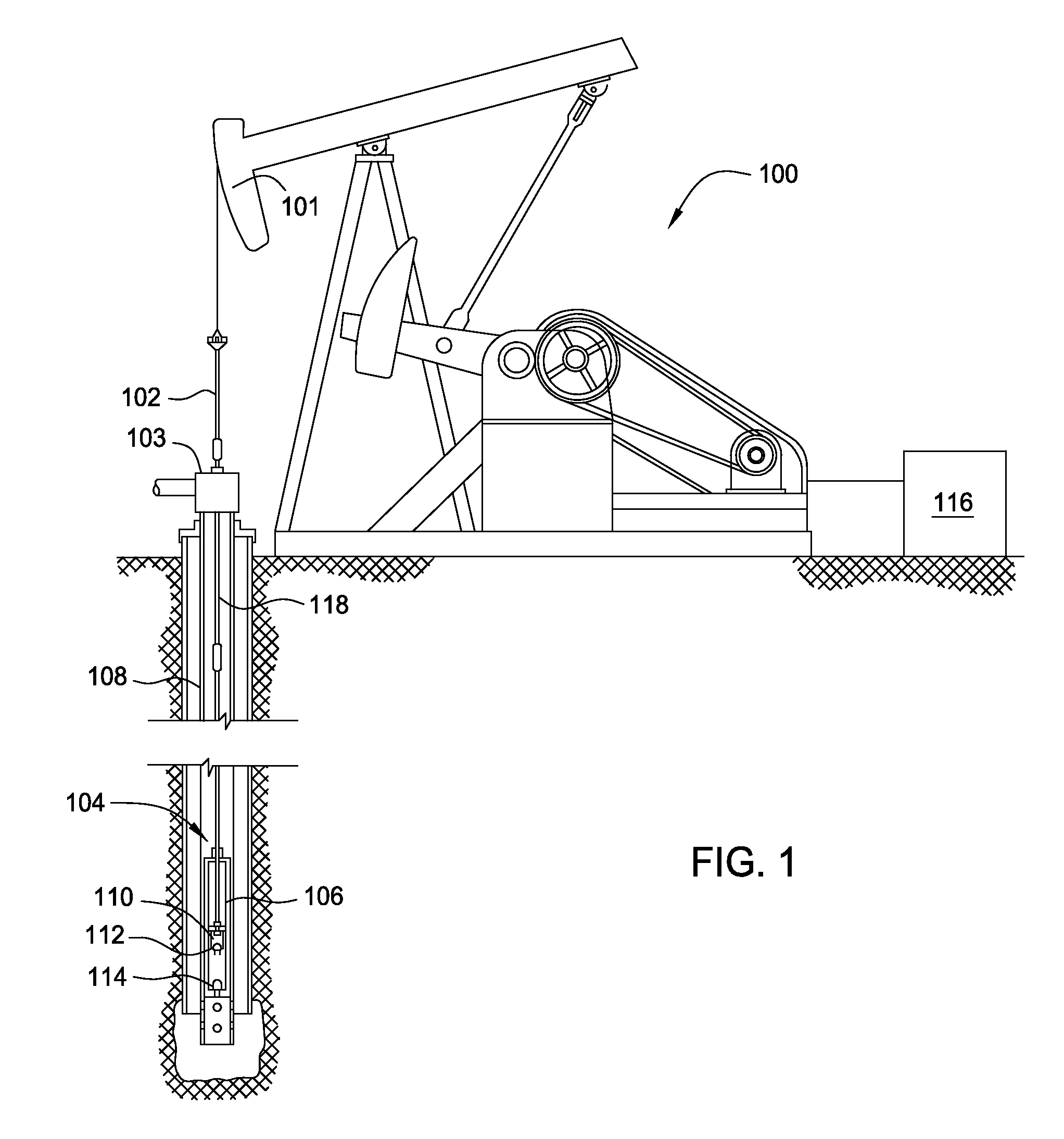
[0023]The production of oil with a sucker-rod pump system 100 such as that depicted in FIG. 1 is common practice in the oil and gas industry. In the pump system 100, a rod pump 104 consists of a tubular barrel 106 with a valve 114 (the “standing valve”) located at the bottom that allows fluid to enter from the wellbore, but does not allow the fluid to leave. Inside the pump barrel 106 is a close-fitting hollow plunger 110 with another valve 112 (the “traveling valve”) located at the top. This allows fluid to move from below the plunger 110 to the production tubing 108 above and does not allow fluid to return from the tubing 108 to the pump barrel 106 below the plunger 110. The ...


PUM


Abstract

Methods and apparatus are provided for determining pump fillage, using data arrays of pump plunger position with respect to time and/or pump plunger load with respect to time. In this manner, well operators may be able to accurately monitor the pump fillage and control the pump accordingly.

Description

CROSS-REFERENCE TO RELATED APPLICATIONS[0001]This application claims benefit of U.S. Provisional Patent Application Ser. No. 61 / 252,000, filed Oct. 15, 2009, which is herein incorporated by reference.BACKGROUND OF THE INVENTION[0002]1. Field of the Invention[0003]Embodiments of the present invention generally relate to estimating efficiency and controlling the operation of a downhole pump disposed in a wellbore. More particularly, embodiments of the present invention generally relate to accurately determining a transfer point of a pump stroke and controlling the pump and fluid production of the well based on the transfer point.[0004]2. Description of the Related Art[0005]The production of oil with a sucker-rod pump is common practice in the oil and gas industry. Typically, the pumping system is designed with the capacity to remove liquid from the wellbore faster than the reservoir may be able to supply liquid into the wellbore. In a fluid-producing well that is aided by artificial l...

Claims


Application Information

Patent Timeline
IPC IPC(8): F04B49/22G06F19/00
CPCE21B43/127E21B47/009
Inventor EHIMEAKHE, VICTORIA M.BOOTH, KEN GEORGE
Owner WEATHERFORD TECH HLDG LLC
Why Eureka
Try Eureka