Eureka AIR delivers breakthrough ideas for toughest innovation challenges, trusted by R&D personnel around the world.

Method, apparatus and system for controlling a movable partition

Active Publication Date: 2011-04-21
WOW DOOR CORP
View PDF99 Cites 31 Cited by
  • Summary
  • Abstract
  • Description
  • Claims
  • Application Information

AI Technical Summary

Benefits of technology

[0025]In accordance with yet another embodiment of the present invention, a method is provided for controlling a movable partition. The method includes coupling at least one roller assembly to a portion of the movable partition and positioning at least one roller element of the at least one roller assembly in contact with a surface of an adjacent structure which the at least one partition will traverse, wherein the surface of the adjacent structure includes at least one substantially nonplanar surface feature. The m

Problems solved by technology

Such lateral displacement of the door's lower edge may be caused, for example, by a fire-induced draft, by an improperly balanced HVAC system, or simply from an occupant of a room pushing against the door while it is being deployed.
If the lower edge of the lead post is laterally displaced relative to its upper edge as the leading edge of the door approaches the mating receptacle, the lead post will not be properly aligned with the mating receptacle and an appropriate seal will not be formed.
If the lower edge of a lead post of a door is laterally displaced relative to its upper edge, the lead post is not plumb (or substantially vertically oriented) and thus will not properly engage the substantially plumb receptacle.
As noted above, the failure of the lead post to properly engage the receptacle may have substantial consequences when, for example, the door is being used as a fire or security barrier.
At a minimum, even when the door is not used as a fire or security barrier, the failure of the lead post to properly engage the mating receptacle will result in the inability to completely subdivide a larger room and visually or acoustically isolate the subdivided room.
However, the placement of a track in the floor of a room is not an ideal solution for all environments.
For example, such a track provides a place for collection of dust and debris and may, thereby, become an unsightly feature of the room.
In some cases, the collection of debris may affect the proper operation of the door itself.
Additionally, the existence of a track in the floor, regardless of whether it is protruding from the floor or recessed within the floor, may act as a hazard or potential source of injury depending, for example, on the intended use of the area and the actual location of the floor track within that area.
Moreover, even if one were to use a track in the floor, floors often exhibit an undesirable amount of unevenness presenting additional difficulties.
For example, it becomes difficult to install an even and level track in a floor or other supporting surface that is not even.
If the track is not substantially even and level, the bottom edge of the partition, or some component associated therewith, may have trouble maintaining engagement with the track while it is being displaced.
Likewise, other devices that may attempt to maintain engagement with (or maintain some other specified relationship with) an adjacent or an underlying surface may experience difficulty doing so due to the unevenness and undulating nature of such a surface.

Method used


Image

  • Method, apparatus and system for controlling a movable partition
  • Method, apparatus and system for controlling a movable partition
  • Method, apparatus and system for controlling a movable partition

Examples


Embodiment Construction

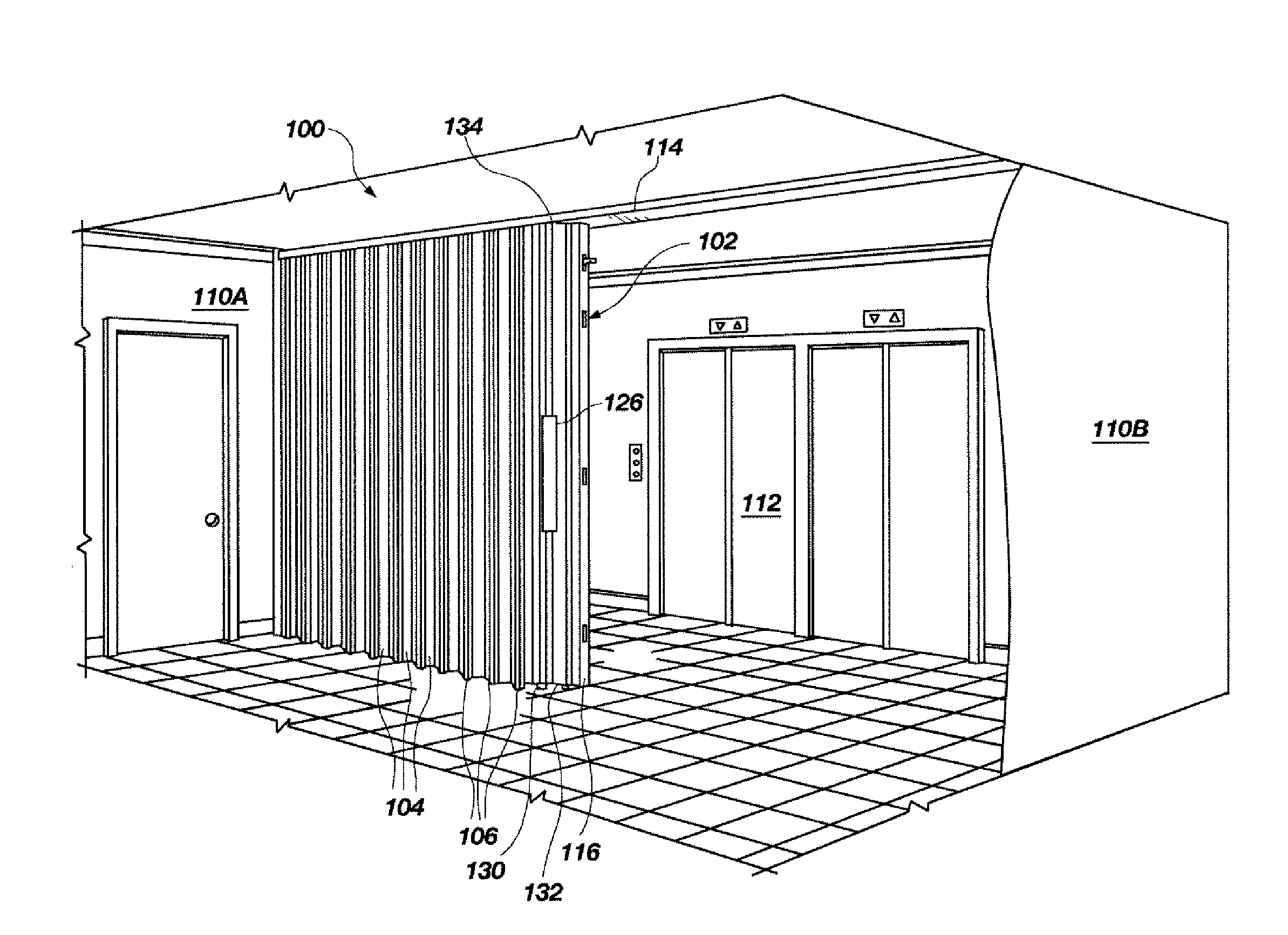
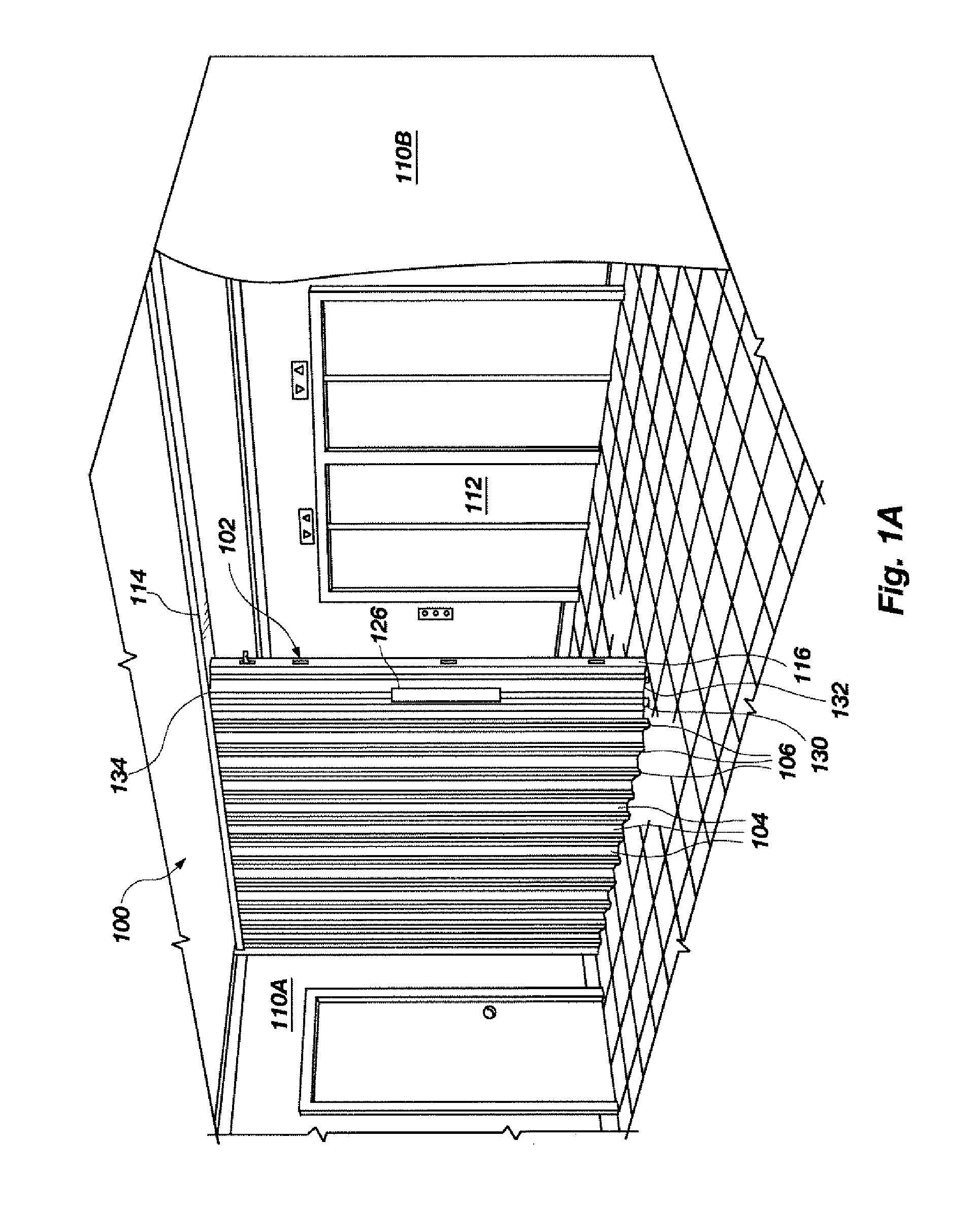
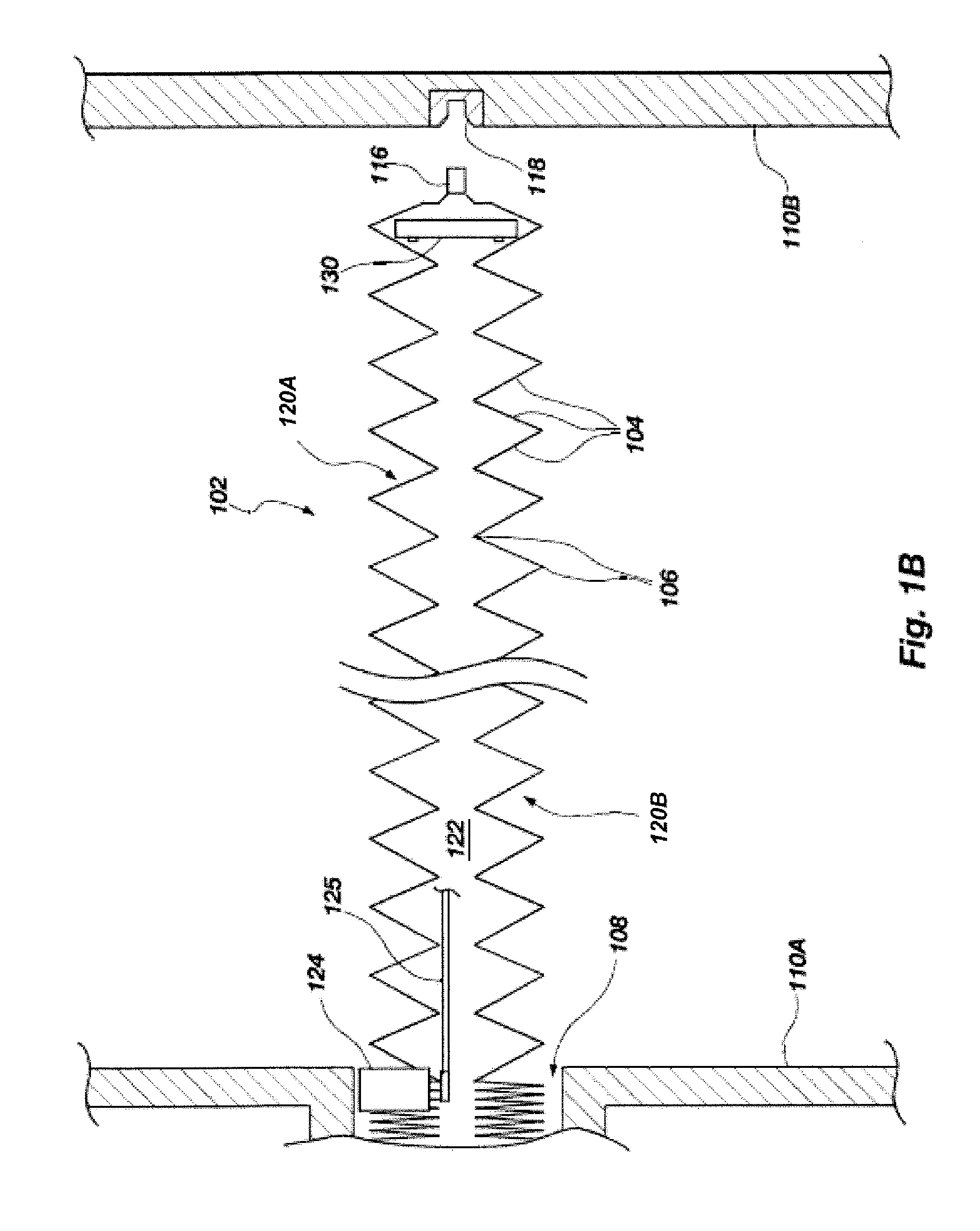
[0046]Referring to FIGS. 1A-1C, a system 100 is shown, which may also be referred to as an automatic door system, including a movable partition in the form of an accordion-type door 102. The door 102 may be used, for example, as a security and / or fire door. In other embodiments, the door 102 need not be utilized as a fire or security door, but may be used simply for the subdividing of a larger space into smaller rooms or areas. The door 102 may be formed with a plurality of panels 104 that are connected to one another with hinges or other hinge-like members 106. The hinged connection of the panels 104 enables the door 102 to be compactly stored or “stacked” in a pocket 108 formed in a wall 110A of a building when in a retracted or folded state.

[0047]When it is desired to deploy the door 102 to an extended position, for example, to secure an area such as an elevator lobby 112 during a fire, the door 102 is driven along a track 114 across the space to provide an appropriate barrier. W...


PUM


Abstract

Various apparatuses, methods and systems for directionally controlling a movable partition are provided. In one embodiment, an apparatus may include at least one roller assembly coupled to a portion of a movable partition. A roller element of the roller assembly may be configured to maintain contact with an adjacent surface (e.g., a floor) while the partition is displaced along a desired path even though the adjacent surface may exhibit unevenness, undulations or other substantially nonplanar surface features. In one embodiment, the apparatus may be configured to maintain a substantially constant force between the roller element and the adjacent surface. In another embodiment, the apparatus may be configured to maintain a force between the roller element and the adjacent surface substantially within a specified range. A steering actuator may also be used to select, or change, the orientation of the roller assembly with respect to the partition.

Description

CROSS-REFERENCE TO RELATED APPLICATION[0001]This application is a divisional of U.S. patent application Ser. No. 11 / 796,325, filed Apr. 27, 2007, pending, the entire contents of which is hereby incorporated herein by this reference.BACKGROUND[0002]1. Field of the Invention[0003]The present invention generally relates to movable partitions and, more particularly, to the control of such partitions including, for example, foldable doors.[0004]2. State of the Art[0005]Movable partitions are utilized in numerous situations and environments for a variety of purposes. Such partitions may include, for example, foldable or collapsible doors configured to enclose or subdivide a room or other area. Often such partitions may be utilized simply for purposes of versatility in being able to subdivide a single large room into multiple smaller rooms. The subdivision of a larger area may be desired, for example, to accommodate multiple groups or meetings simultaneously. In other applications, such pa...

Claims


Application Information

Patent Timeline
IPC IPC(8): G05D3/14A47G5/00
CPCE05D15/26E05Y2900/142E06B3/94E05F15/70E05F15/20E05F15/605E05Y2400/33
Inventor GOODMAN, E. CARLFIELD, D. GEORGEBANTA, KEVIN D.
Owner WOW DOOR CORP
Why Eureka
Eureka Blog
Learn More