

Method for displaying 3D image by using the binocular disparity in mobile terminal and mobile terminal using the same
a mobile terminal and binocular disparity technology, applied in the field of mobile terminals and corresponding methods for displaying 3d images using binocular disparity, can solve the problems of difficult operation or seeing the variety of different functions provided on the terminal, and achieve the effect of convenient and more visible to the user
- Summary
- Abstract
- Description
- Claims
- Application Information
AI Technical Summary
Benefits of technology
Problems solved by technology
Method used
Image

Examples
first embodiment
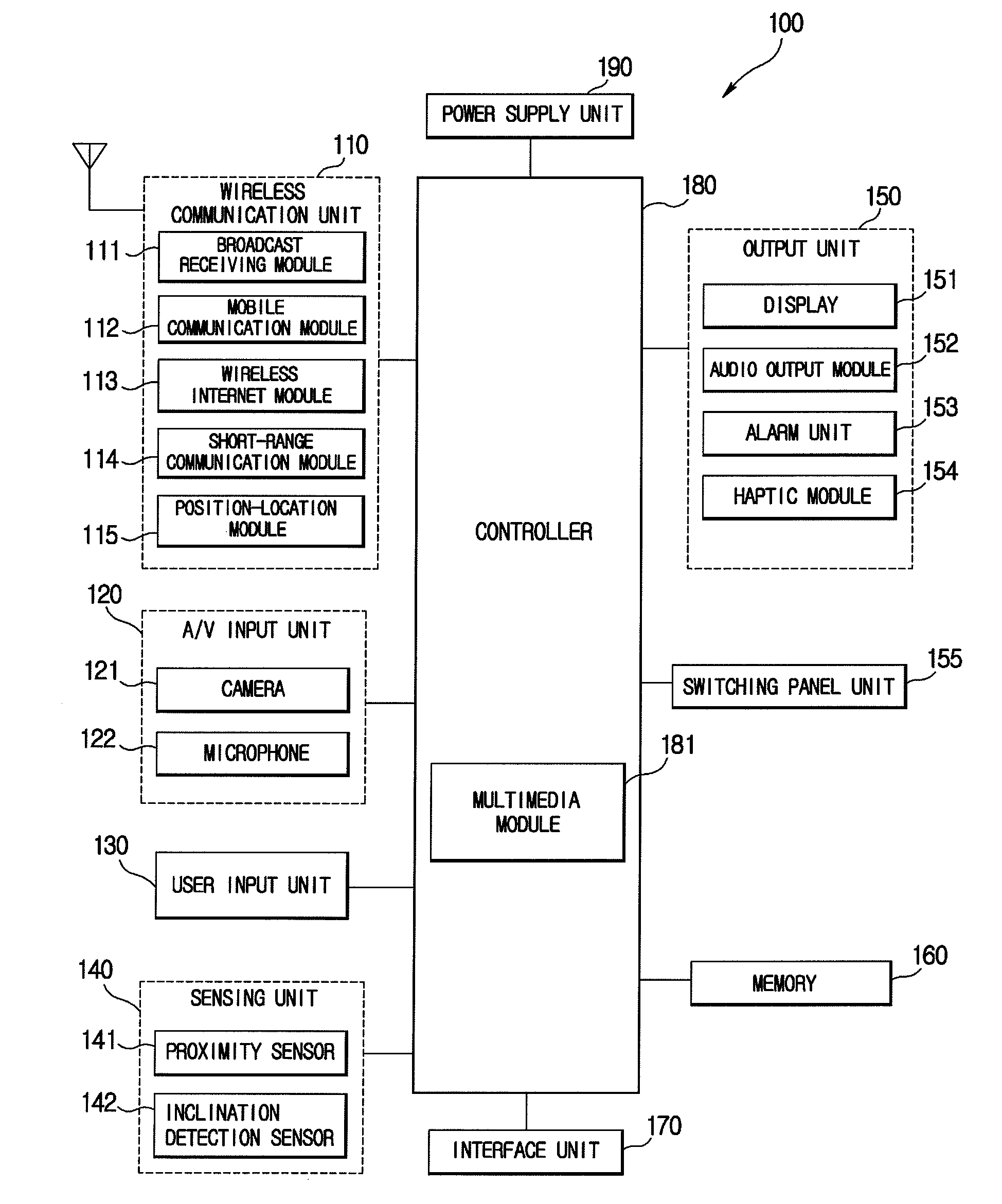
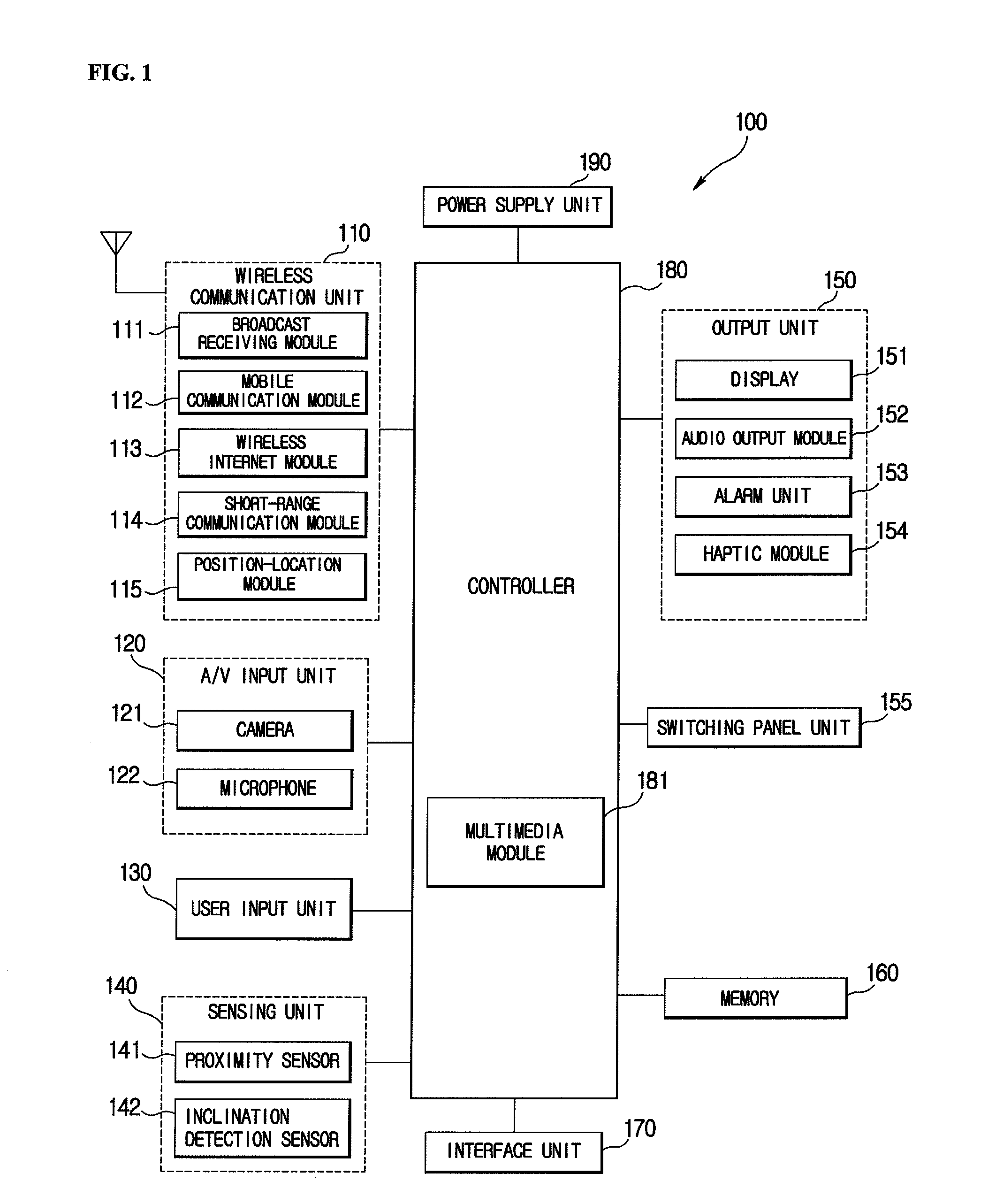
[0083]Next, a method for displaying a 3D image using binocular disparity in a mobile terminal according to an embodiment of the present invention will be described with reference to the flowcharts of FIGS. 4-6. Referring to FIG. 4, which illustrates the present invention, the user provides 3D attributes to an image through the user input unit (S1). The set 3D attributes may include an adjustment of depth, swinging of light, providing of light, change of surface color, providing of a 3D color, etc. The setting of the 3D attribute will be further described in more detail later with reference to FIGS. 8A-14. Further, the image may include an icon, an image object, a text, an emoticon, a moving picture image and a still image.
[0084]Referring again to FIG. 4, when the condition is met after the 3D attribute is provided, the switching panel unit 155 is turned on (S2), and the controller 180 displays a left eye image and a right eye image on the display 151 (S3). At this time, the left eye...
second embodiment
[0085]Next, FIG. 5 is a flowchart illustrating the present invention. Referring to FIG. 5, the memory 160 stores a 3D imaginary spatial image (S11). Also, the 3D imaginary spatial image includes the left eye image and the right eye image, and as the switching panel unit 155 is turned on, the left eye image and the right eye image are respectively viewed through a left eye and a right eye of the user to complete the 3D image. That is, when the 3D imaginary spatial image is displayed on the display 151, which is a touch screen, the switching panel unit 155 is turned on to display the image as a 3D image (S12).
[0086]At this time, only a part of the imaginary spatial image is displayed on the touch screen. Under this circumstance, the controller 180 checks if an inclination detection signal of the mobile terminal has been generated by the inclination detection sensor 142 (S13). When the inclination detection signal is generated (Yes in S13), the controller 180 changes the display of the...
third embodiment
[0088]Next, FIG. 6 is a flowchart illustrating the present invention. Referring to FIG. 6, the memory 160 stores a 3D imaginary spatial image and the 3D imaginary spatial image includes a 3D icon. The 3D imaginary spatial image and the 3D icon are also displayed on the touch screen (S21). Further, the 3D imaginary spatial image and the 3D icon include the left eye image and the right eye image, and as the switching panel unit 155 is turned on, the left eye image and the right eye image can be respectively viewed through a left eye and a right eye of the user to complete the 3D image. That is, as discussed above, the switching panel unit 155 is turned on to allow the 3D image to be displayed as a real 3D image.
[0089]At this time, only a part of the 3D imaginary spatial image is displayed on the touch screen. Meanwhile, the touch screen is a constant current constant voltage combined touch screen capable of receiving all the constant current and constant voltage inputs. When only cons...
PUM
 Abstract
Description
Claims
Application Information