
Accurate and rapid micromixer for integrated microfluidic devices

a micromixer and microfluidic technology, applied in the direction of mechanical equipment, machines/engines, transportation and packaging, etc., can solve the problems of difficult mixing in these chips, general diffusion limitation, and difficulty in a number of applications,

Active Publication Date: 2011-05-05
RGT UNIV OF CALIFORNIA
View PDF17 Cites 35 Cited by
  • Summary
  • Abstract
  • Description
  • Claims
  • Application Information

AI Technical Summary

Benefits of technology

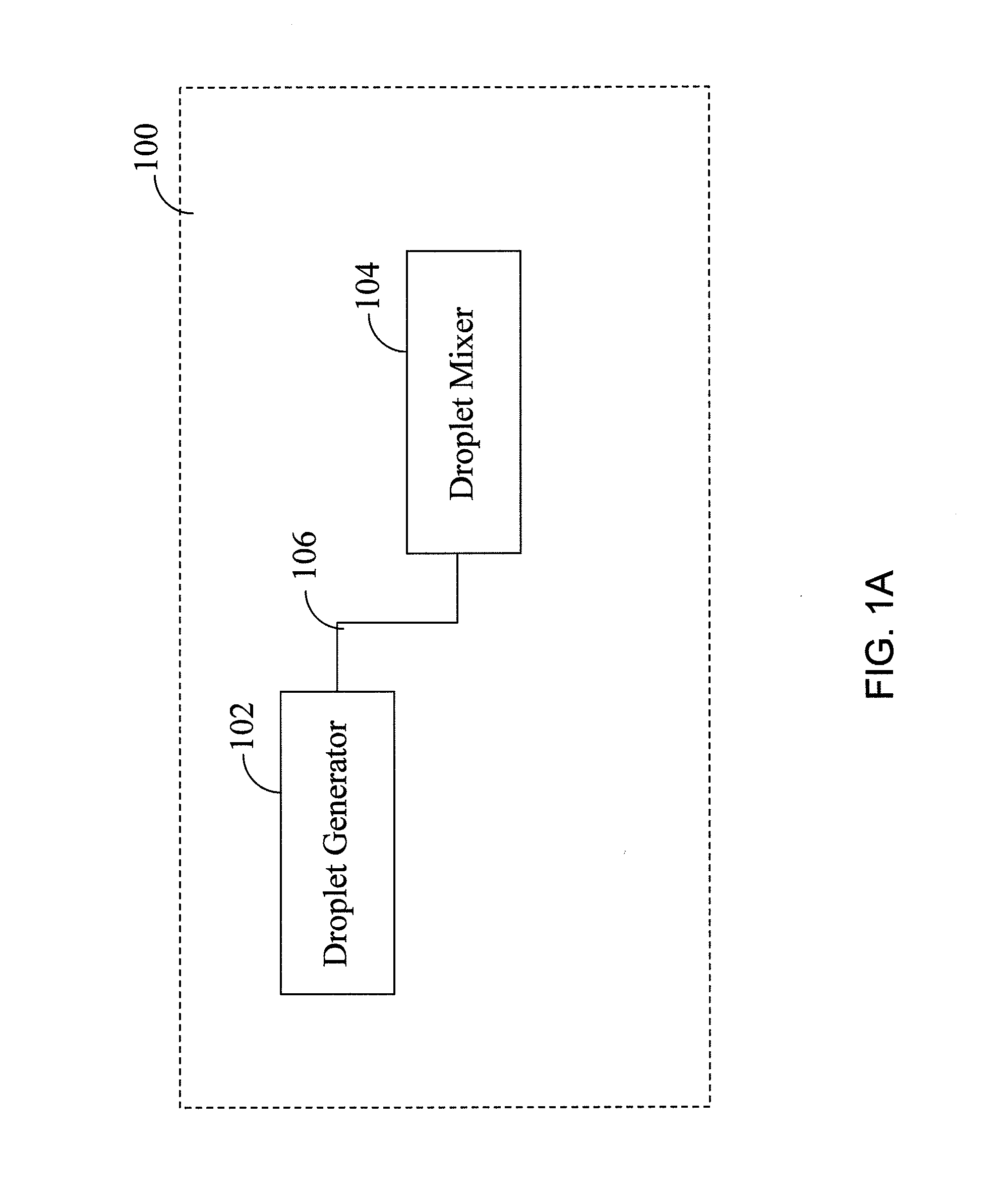
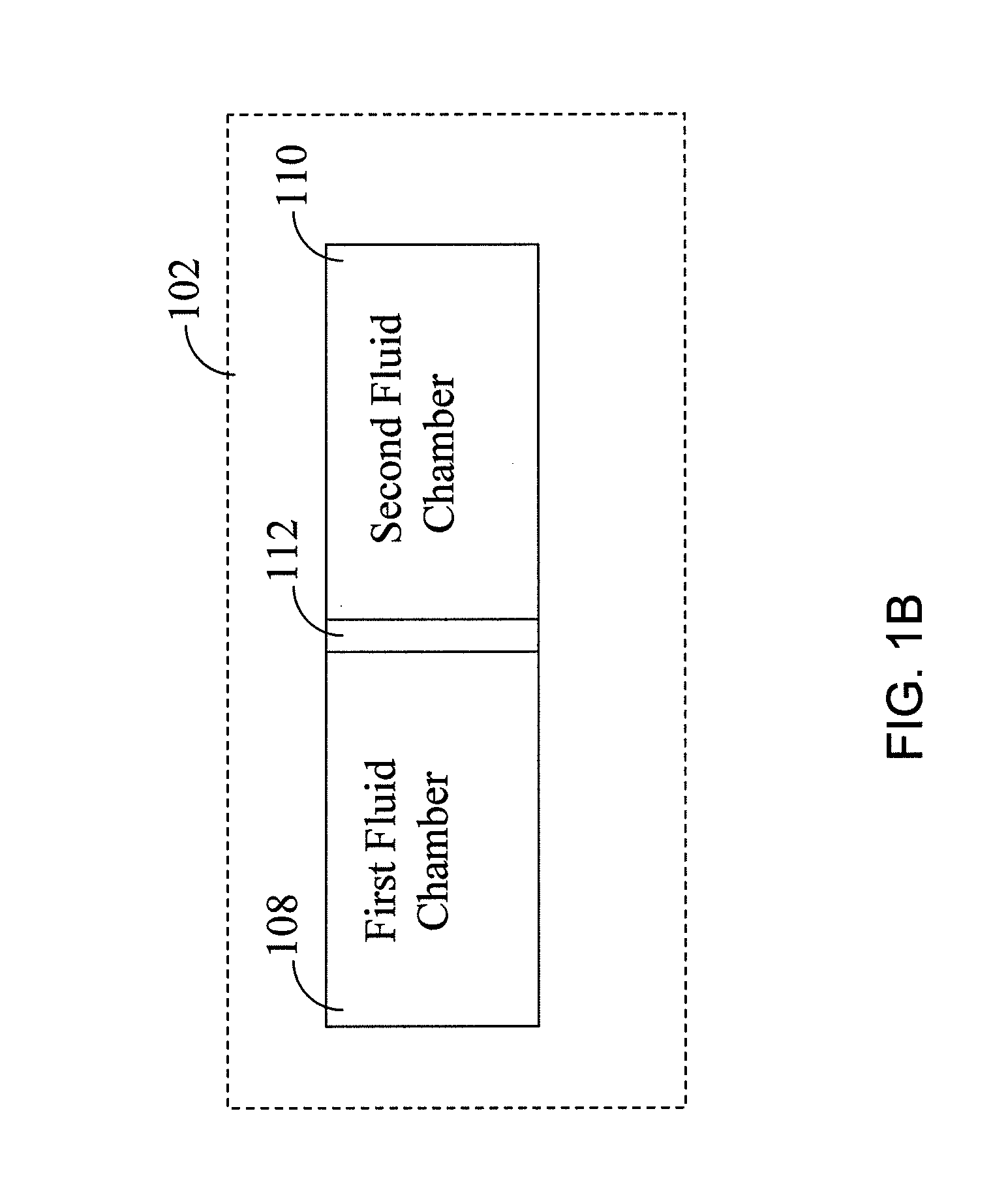
[0014]Some embodiments of the current invention provide a microfluidic mixer having a droplet generator and a droplet mixer in selective fluid connection with the droplet generator. The droplet generator comprises first and second fluid chambers that are structured to be filled with respective first and second fluids that can each be held in isolation for

Problems solved by technology

Mixing in these chips is challenging due to the absence of turbulence under most normal operating conditions due to low Reynold's number.
As is well known in the art, the mixing rate is generally limited by diffusion.
Although fast mixing may be achieved, the implementation is difficult for a number of applications, especially those using low volumes of at least one reagent.
This is because it is hard to make the reagents that are being mixed arrive at the mixing junction exactly at the same time.
Quite often, some droplets have to be discarded due to, for example, incorrect volume ratios.
Furthermore, flow rates and other parameters must be laboriously tuned with care since operation depends on, for example, temperature, viscosity, type of solvents, number of reagents, desired volume ratios, etc.
Generation of series of droplets having different sizes, volume ratios, etc. is especially difficult and many droplets must be discarded in the transition interval as operating parameters are altered.
The rotary mixer and its variations, however, are not scalable designs.
As the volume / length of the mixer increases, a longer time is required for circulating the fluids, and the effectiveness of pumping diminishes.
Furthermore, the rotary mixer and its variations are sensitive to the presence of bubbles, which may occur in a reaction resulting in the fluids being heated above the boiling point or the release of gas.

Method used


Image

  • Accurate and rapid micromixer for integrated microfluidic devices
  • Accurate and rapid micromixer for integrated microfluidic devices
  • Accurate and rapid micromixer for integrated microfluidic devices

Examples


Embodiment Construction

[0024]Some embodiments of the current invention are discussed in detail below. In describing embodiments, specific terminology is employed for the sake of clarity. However, the invention is not intended to be limited to the specific terminology so selected. A person skilled in the relevant art will recognize that other equivalent components can be employed and other methods developed without departing from the broad concepts of the current invention. All references cited herein are incorporated by reference as if each had been individually incorporated.

[0025]Herein the terms “microfluidic chip”, “microfluidic chip system”, “chip”, “microfluidic device” may be used interchangeably without significantly changing the context of the disclosure. Specifically, the “microfluidic chip system” refers to the microfluidic chip and other components going into and out of the chip, whereas “chip” and “microfluidic chip” both refer to the microfluidic chip alone. A “microfluidic device” refers to ...


PUM


Abstract

The invention may provide a microfluidic mixer having a droplet generator and a droplet mixer in selective fluid connection with the droplet generator. The droplet generator comprises first and second fluid chambers that are structured to be filled with respective first and second fluids that can each be held in isolation for a selectable period of time. The first and second fluid chambers are further structured to be reconfigured into a single combined chamber to allow the first and second fluids in the first and second fluid chambers to come into fluid contact with each other in the combined chamber for a selectable period of time prior to being brought into the droplet mixer.

Description

CROSS-REFERENCE OF RELATED APPLICATION[0001]This application claims priority to U.S. Provisional Application No. 61 / 006,551 filed Jan. 18, 2008, the entire contents of which are hereby incorporated by reference.[0002]The invention was made with Government support of Grant No. DE-FG-06ER64249 awarded by the Department of Energy and Grant No. U54 CA119347-02 awarded by the National Institutes of Health. The United States Government has certain rights in the invention.BACKGROUND[0003]1. Field of Invention[0004]The current invention relates to microfluidic devices, and more particularly to microfluidic devices that include a droplet generator.[0005]2. Discussion of Related Art[0006]Thorough mixing is paramount for performing chemical or biochemical reactions to achieve high and repeatable yields. Rapid mixing improves desired reactions by avoiding side reactions caused by, for example, large excess of one reagent in uneven distribution. Speed of mixing may be particularly important in c...

Claims


Application Information

Patent Timeline
IPC IPC(8): B01F15/02F15D1/00
CPCB01F15/0462B01F13/0071Y10T137/8593B01F33/3021B01F35/8822
Inventor VAN DAM, R. MICHAELLIU, KANSHEN, KWANG-FU CLIFTONTSENG, HSIAN-RONG
Owner RGT UNIV OF CALIFORNIA
Learn More