Integrated aerated bubble generating device

a generation device and aerated bubble technology, applied in water installations, domestic plumbing, construction, etc., can solve the problems of hindering the aesthetic unity of the modern interior space, prone to user damage, and external placement, so as to reduce the chance of unwanted damage to the device and maintain the overall aesthetic unity of the interior spa

Inactive Publication Date: 2011-05-19
CASHIDO
View PDF1 Cites 2 Cited by
  • Summary
  • Abstract
  • Description
  • Claims
  • Application Information

AI Technical Summary

Benefits of technology

[0007]The object of the present invention is to disclose an aerated bubble generating device, integrated into water-supply means and creating fine bubbles so as to be capable of being integrated into existing water-supply equipments, such as the faucet or the shower head. Furthermore, the unit may be integrated into the water supply equipment in a concealed location, thereby reducing the chance of unwanted damage to the device and also maintaining overall aesthetic unity of the interior space.

Problems solved by technology

The external add-on units not only occupy precious space, the external placement makes them more prone to user damage.
Moreover, the lack of integration of an add-on unit would hinder the aesthetic unity of the modern interior space.

Method used


Image

  • Integrated aerated bubble generating device
  • Integrated aerated bubble generating device
  • Integrated aerated bubble generating device

Examples


first embodiment

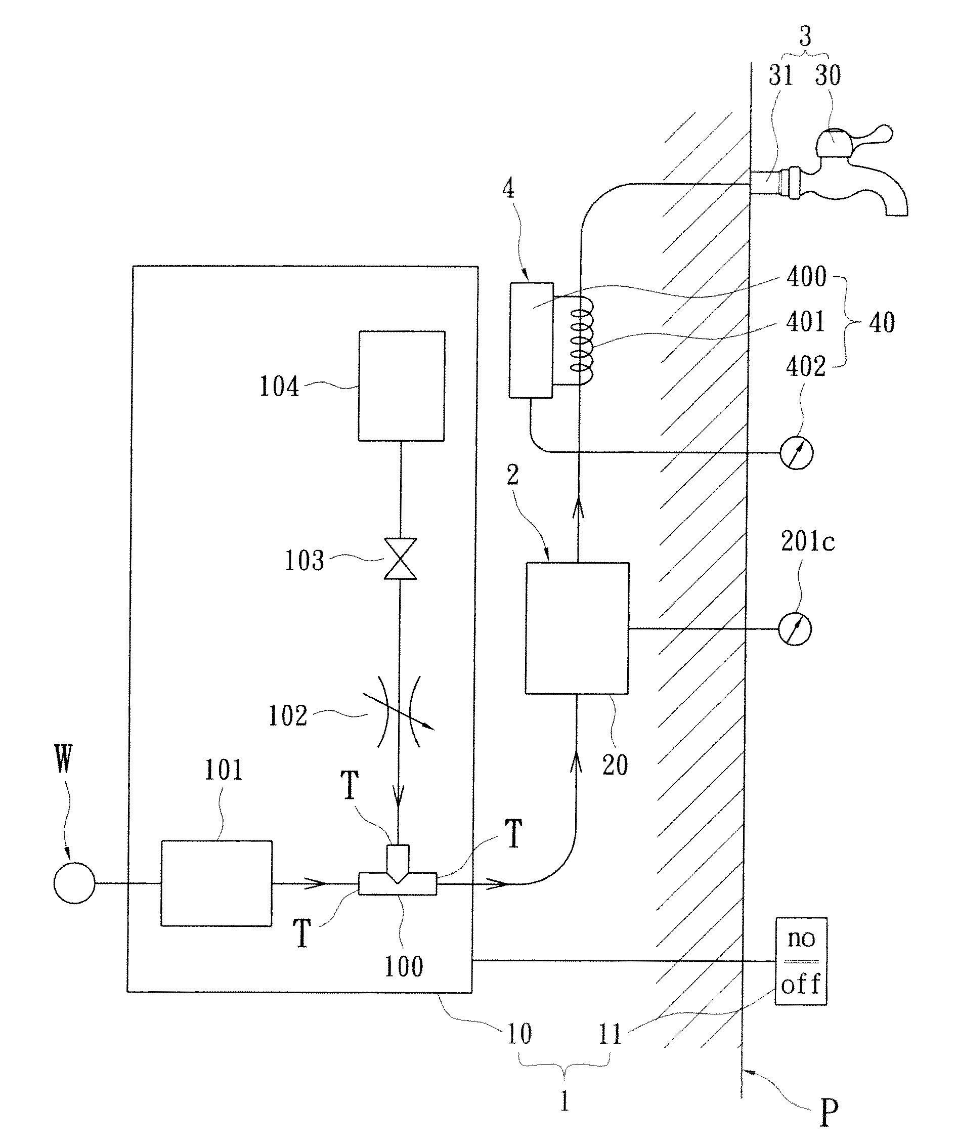
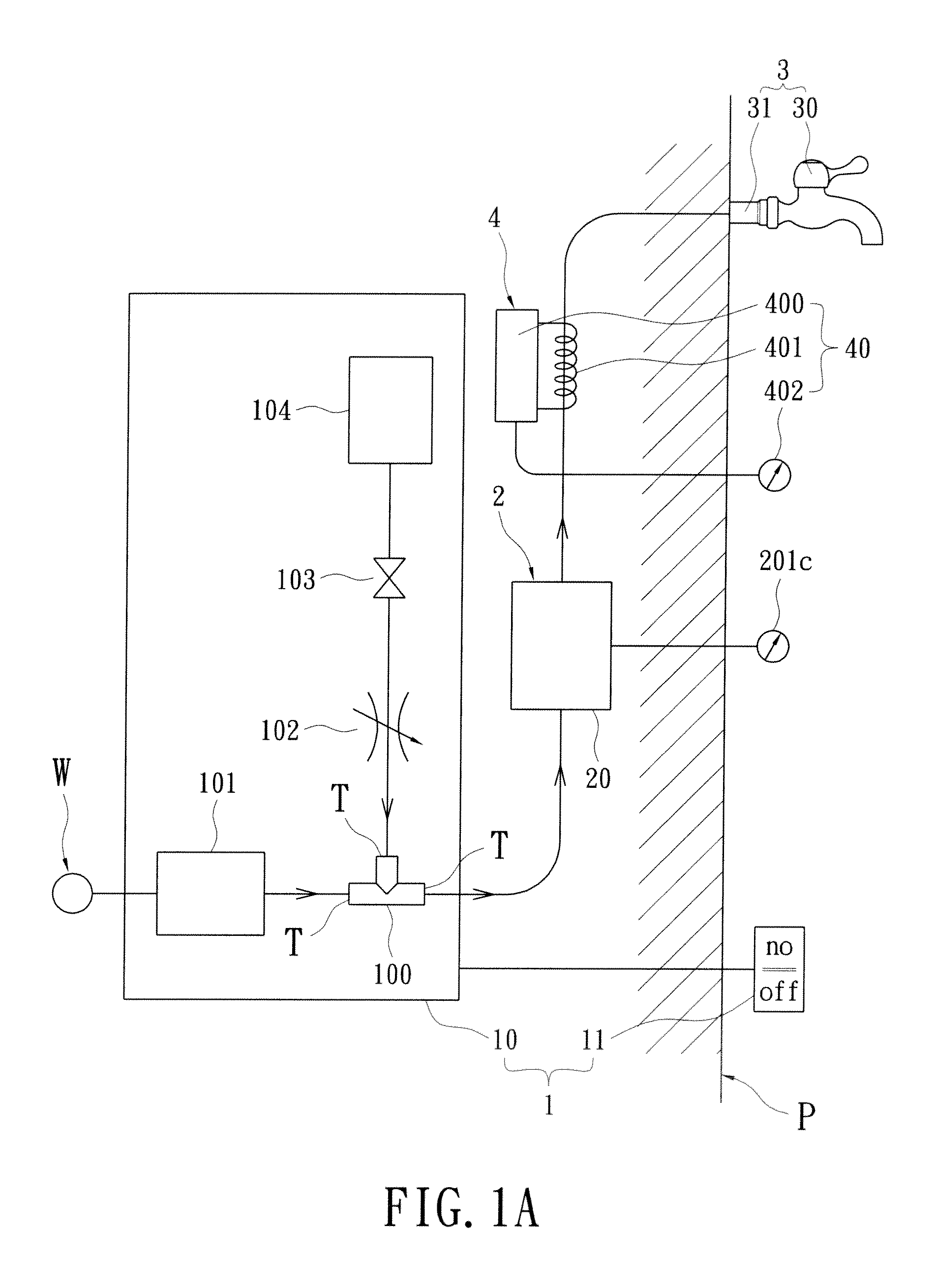
[0030]The water discharge unit further includes a heating unit 4 arranged in the predetermined object P. The heating unit 4 has at least one heating device 40, which is disposed between the bubble density-adjustment device 20 and the water-supply device 30 so as to heat the communicating pipe 31. In that case, the heating device 40 includes a heater 400, a heating strip 401 and a temperature controller 402. The heating strip 401 links the heater 400 and encircles the communicating pipe 31, and the temperature controller 402 electrically connects the heater 400, for switching the heater 400 and adjusting the heat generated by the heating strip 401.

[0031]With respect to FIG. 2, the aerated bubble generating device according to a second embodiment is installed in the predetermined object P, which is a wall, a casing or anything encircling the besprinkling facility. The difference between the first and second embodiments is the water-supply device 30 is a fixed shower head, for example...

fourth embodiment

[0033]With respect to FIG. 4, the aerated bubble generating device is installed in the predetermined object P, which is a wall, a casing or anything encircling the besprinkling facility. The aerated bubble generating device includes a bubble generation unit 1, a bubble density-adjustment unit 2 and a besprinkling unit 3.

[0034]The main difference between the first and fourth embodiments is that the bubble generation device includes a three-way pipe 100, a liquid pressure-boost pump 101, a flow adjustment valve 102, an electromagnetic valve 103, and a gas pressure-boost pump 104. The three-way pipe 100 defines three exits T. One of the exits T communicates with the water source W. The liquid pressure-boost pump 101 defines two ends communicating with a respective one of the distal ends of the bubble density-adjustment device 20 and another one of the exits of the three-way pipe 100. The flow adjustment valve 102 has an end connecting the last one of the exits of the three-way pipe 10...


PUM


Abstract

An aerated bubble generating device, integrated into water-supply means and creating fine bubbles, includes a bubble generation unit, a bubble density-adjustment unit and a water discharge unit. The bubble generation unit has a bubble generation device arranged in the predetermined object and a switch electrically connecting to the bubble generation device and exposed out of the predetermined object. The bubble density-adjustment unit has a bubble density-adjustment device arranged in the predetermined object, for controlling the size of each bubble. The bubble density-adjustment device defines a distal end linking the bubble generation device. The water discharge unit has a water-supply device exposed out of the predetermined object and a communicating pipe linking both of the bubble density-adjustment and the water-supply devices.

Description

BACKGROUND OF THE INVENTION[0001]1. Field of the Invention[0002]The present invention relates to a bubble generating device; in particular, to an aerated bubble generating device integrate-able and concealedly adapted to water-supply equipments for generating bubbles.[0003]2. Description of Related Art[0004]Taking baths is a popular enjoyment for busy, overstressed modern people. Many novel bathing equipment besides the traditional bath tubs are created to further enhance the relaxing experience. The massage tubs, the SPA machines, and the milk bath generating machines are examples of such products.[0005]Among the bathing products, to milk bath generator is a relatively novel product on market today. Unlike traditional milk baths that actually employ dry milk power into bathing water, modern milk bath generators create tiny air bubbles in the bathing water by pressurizing the air and water; the created bubbles are so fine that they make the water look milky white, therefore obtainin...

Claims


Application Information

Patent Timeline
Patent Type & Authority Applications(United States)
IPC IPC(8): E03C1/08
CPCE03C1/046E03C1/044
Inventor CHEN, SHIH-CHANGCHEN, CHIH-HSIANG
Owner CASHIDO
Why Eureka
Try Eureka