Imaging device

Active Publication Date: 2011-05-19
PANASONIC CORP
View PDF6 Cites 4 Cited by
  • Summary
  • Abstract
  • Description
  • Claims
  • Application Information

AI Technical Summary

Benefits of technology

[0020]The imaging device of the present invention is designed so that a plate member such as a sheet metal is held by a holding member using a number of fastening members to be introduced through a fixing hole of a first portion of the plate member and an adjusting hole of a second portion thereof. As the first and second portions are not integrated together, the first portion can be fixed using the fixing hole, and the relative position of the second portion to the holding member (e.g., the tilt of the second portion with respect to the optical axis) can be adjusted at the same time. Among other things, since the first portion is fixed on the holding member, the tilt of the second portion can be adjusted with stability.
[0021]In addition, as a resilient member is arranged so as to surround the space between multiple optical members, at least one of those optical members contacts with the resilient member on the sloped portion of the resilient member that is tilted with respect to the optical axis. Since the optical member is arranged to avoid contact with the resilient member at the top of the sloped portion, the space can be closed up securely using a simple structure, thereby preventing safely any dust from entering the device.

Problems solved by technology

This is because unless the optical axis is perpendicular to the imager, the subject's image will be captured non-uniformly on the CCD, thus eventually getting the subject's image blurred.
However, this is a very inefficient method.

Method used


Image

  • Imaging device
  • Imaging device
  • Imaging device

Examples


Embodiment Construction

[0037]Hereinafter, embodiments of an imaging device according to the present invention will be described with reference to the accompanying drawings. In the following description, the imaging device is supposed to be implemented as a digital camera.

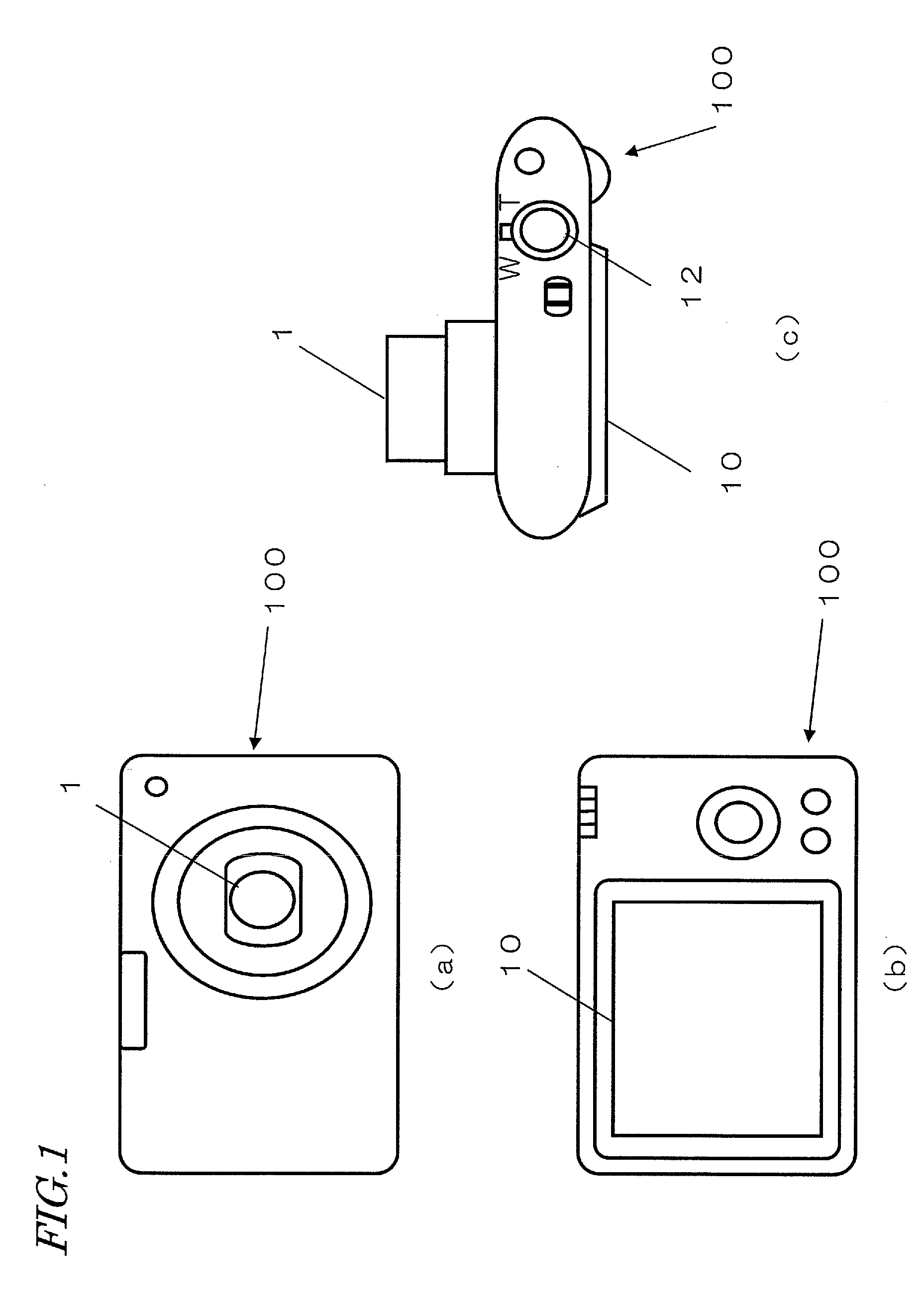
[0038]FIGS. 1(a), 1(b) and 1(c) are respectively a front view, a rear view and a top view illustrating the general appearance of a digital camera 100 as an embodiment of the present invention.

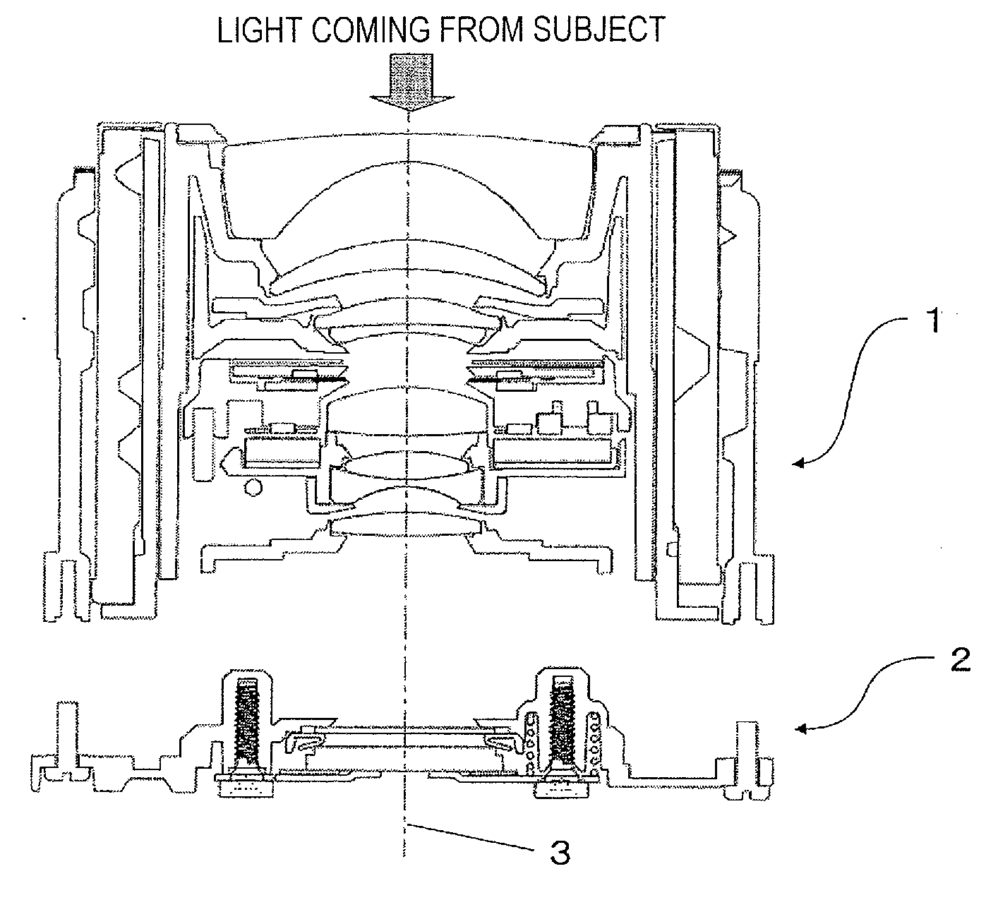
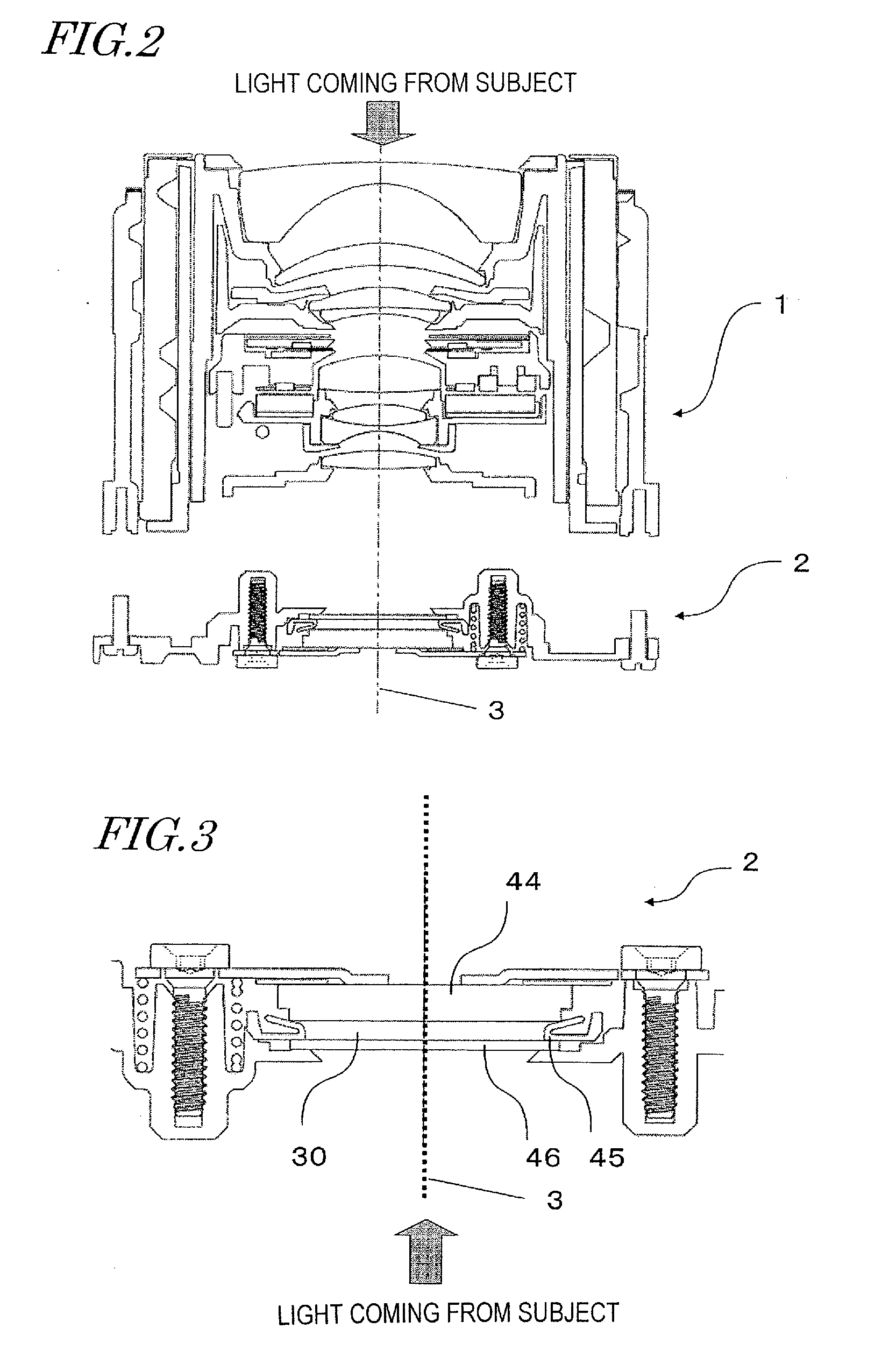
[0039]The digital camera 100 includes a barrel 1. The light that has come from the subject to shoot enters the barrel 1, goes through an optical system in the digital camera 100, and is imaged on an imager (which may be a CCD according to this embodiment) to be described later. The imager outputs an electrical signal representing the intensity of the light received. Thereafter, the electrical signal is digitized to generate video data. An image represented by the video data is presented on the LCD monitor 10 shown in FIG. 1(b). And when the shutter r...


PUM


Abstract

To produce a subject's image on an imager as accurately as possible, a technique that is effectively applicable to the process of assembling an optical system is provided.An imaging device includes: an imager; a plate member, to which the imager is attached; and a holding member configured to hold the plate member. The plate member has a first portion, through which at least one fixing hole has been cut, and a second portion, to which the imager is attached and through which at least one adjusting hole has been cut. The plate member is held by the holding member using a number of fastening members to be introduced through the at least one fixing hole and the at least one adjusting hole. When the first portion is fixed on the holding member, the fastening member that is introduced through the at least one adjusting hole adjusts the relative position of the second portion to the holding member.

Description

TECHNICAL FIELD[0001]The present invention relates to an imaging device including an imager, and more particularly relates to a technique for assembling an optical system in an imaging device including an imager.BACKGROUND ART[0002]In a so-called “digital camera”, arranged are various kinds of optical elements including lenses and an imager (such as a CCD). In order to produce a subject's image as accurately as possible on an imager, improvements have been added to not only the performance of the respective optical elements themselves but also the shapes and arrangement of members that support those optical elements.[0003]For example, Patent Document No. 1 discloses a technique for preventing dust from heading for an imager by providing packing between the imager and an optical element that is located adjacent to the imager. Various shapes have been proposed for that packing. Patent Document No. 1 discloses packing in one shape as shown in FIG. 5 of the document and packing in a mod...

Claims


Application Information

Patent Timeline
IPC IPC(8): H04N5/225
CPCH04N5/2253G03B17/02H04N23/54
Inventor KONISHI, AKIOHIRABAYASHI, KOICHIROSAKAMOTO, KEIJIITO, DAISUKENAGASAKI, EIJI
Owner PANASONIC CORP
Why Eureka
Try Eureka