High speed feedback adjustment of power charge/discharge from energy storage system

a technology of energy storage system and power charge, which is applied in the direction of non-electric variable control, process and machine control, instruments, etc., can solve the problems of large energy storage capacity, non-intelligent discharge feeding load, and prevailing cost of energy storag

Active Publication Date: 2011-05-19
STEM
View PDF80 Cites 36 Cited by
  • Summary
  • Abstract
  • Description
  • Claims
  • Application Information

AI Technical Summary

Benefits of technology

The invention describes a smarter way for charging electronic devices connected to an electrical grid. It uses sensors placed throughout the device's environment to gather data about its usage patterns during different times of day. This data is then sent back to a central controller, which analyzes it and sends instructions to recharge or discharge the battery accordingly. By doing this, the system ensures efficient use of power and reduces wasted energy consumption.

Problems solved by technology

Traditional electricity distribution systems often store too much energy when there's no way to quickly use it, leading to high costs and wasted resources. They also fail to align power delivery with actual needs, causing unnecessary waste and increased fuel usage. There is a technical problem that requires smarter and more efficient ways to manage power charges and discharges.

Method used


Image

  • High speed feedback adjustment of power charge/discharge from energy storage system
  • High speed feedback adjustment of power charge/discharge from energy storage system
  • High speed feedback adjustment of power charge/discharge from energy storage system

Examples


Embodiment Construction

[0016]While preferable embodiments of the invention have been shown and described herein, it will be obvious to those skilled in the art that such embodiments are provided by way of example only. Numerous variations, changes, and substitutions will now occur to those skilled in the art without departing from the invention. It should be understood that various alternatives to the embodiments of the invention described herein may be employed in practicing the invention.

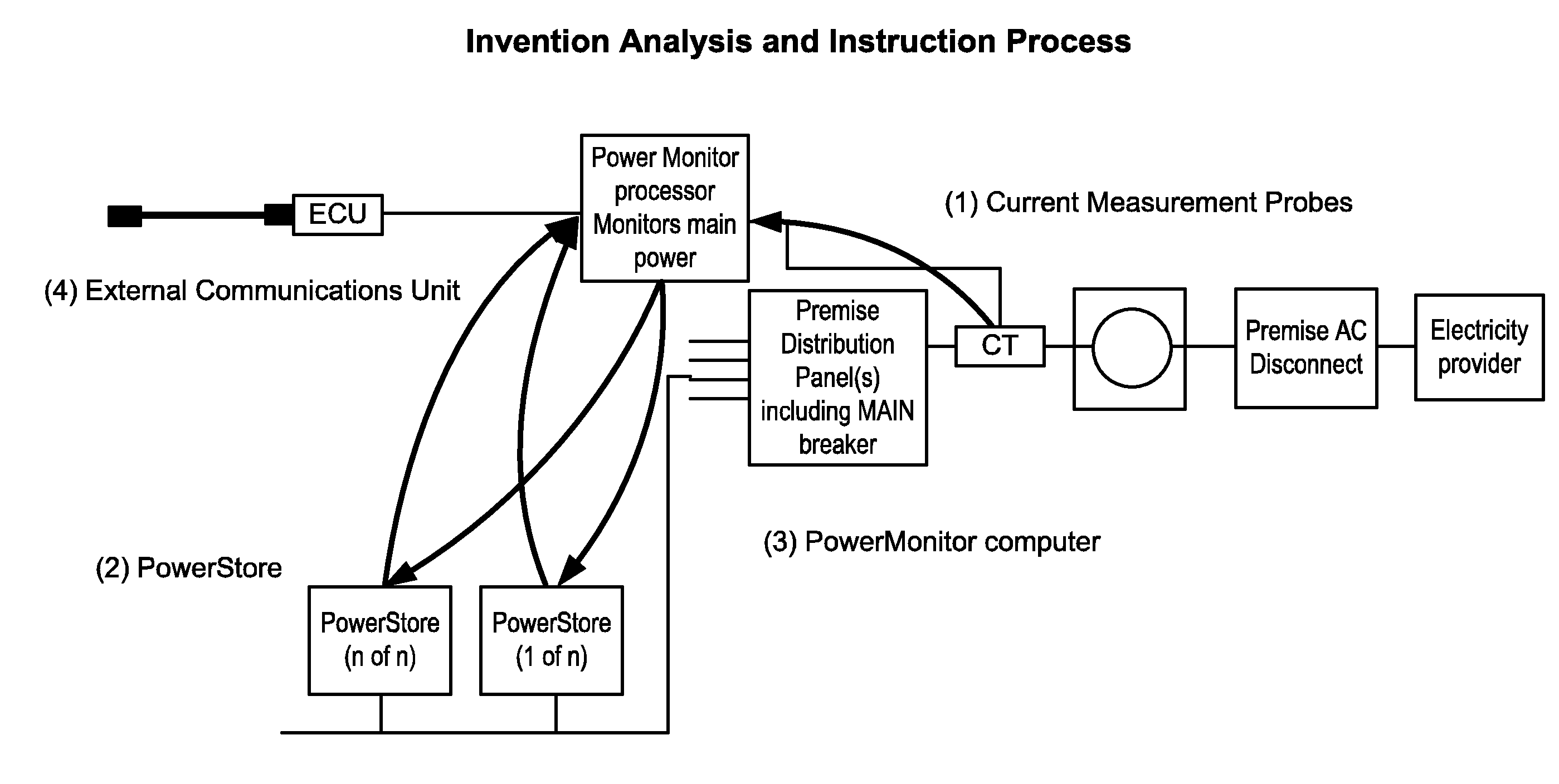
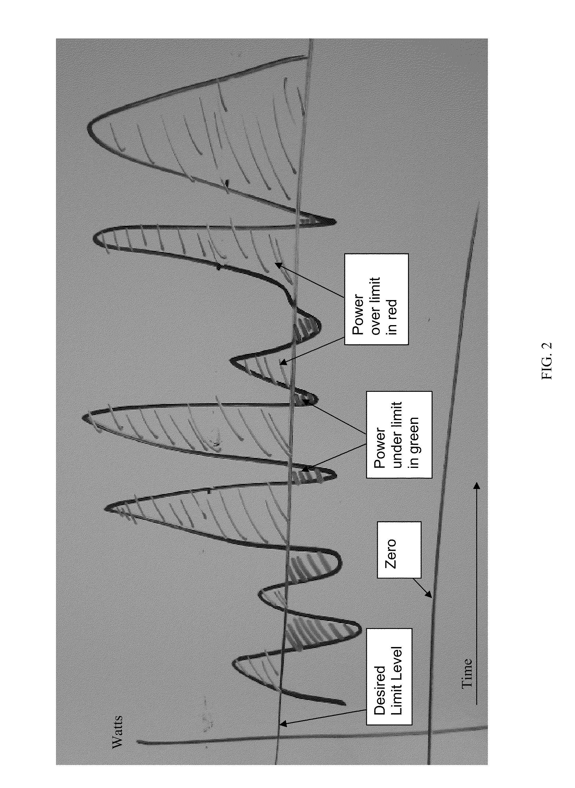
[0017]The invention provides systems and methods for control of power charge / discharge from energy storage system. Such configurations may include high speed feedback power adjustment. Various aspects of the invention described herein may be applied to any of the particular applications set forth below or for any other types of power generation, control and distribution. The invention may be applied as a standalone system or method, or as part of an integrated power delivery or control system. It shall be understood tha...


PUM


Abstract

The invention provides systems and methods for control of power charge/discharge from energy storage system. The invention also provides for power monitoring and management. A smart charge system may include a system sensor, one or more energy storage units, and a controller, which may receive information about the power demand, power provided by an electricity provider, and charge/discharge information from an energy storage unit. The information received may all be time synchronized in relation to a time based reference. The controller may provide instructions to an energy storage unit at a rapid rate.

Description


Claims


Application Information

Patent Timeline
Owner STEM
Why Eureka
Try Eureka