Apparatus and methods for digital manufacturing

a digital manufacturing and apparatus technology, applied in the field of manufacturing objects/materials, can solve the problems of affecting the quality of materials,

Active Publication Date: 2011-05-26
CORNELL UNIVERSITY
View PDF60 Cites 43 Cited by
  • Summary
  • Abstract
  • Description
  • Claims
  • Application Information

AI Technical Summary

Benefits of technology

[0009]In one embodiment, the system for manufacturing object/materials of these teachings includes a component arranging subsystem receiving a number of components and arranging the received components in a feeder area, one location in an arrangement corresponding to a location of one component, an assembly head including a printhead structural subsystem having a number of selectively activatable locations on one surface, each selectively activatable location corresponding to a location in the arrangement; upon activation, one component is operatively attached to one selectively activated location upon disposing the printhead structural subsystem on the ar

Problems solved by technology

Most conventional manufacturing techniques can be considered analog since the conventional manufacturing techniques are practically continuous, their substructure cannot be arbitrarily specified and accuracies lost with each measurement and subsequent application.
Conventional three-dimensional printing processes are generally material-dependent and irreversible.
In order to make high-resolution objects, they need to be very precise, and therefore they cost between tens and hundreds of thousands of dollars and must be operated by skilled technicians.
Recent manufacturing techniques such as bottom-up self assembly offer some of the benefits of digital matter in their ability to spontaneously assemble materials guided by local interactions between components; however, self-a

Method used


Image

  • Apparatus and methods for digital manufacturing
  • Apparatus and methods for digital manufacturing
  • Apparatus and methods for digital manufacturing

Examples


Embodiment Construction

[0022]Embodiments of digital manufacturing systems and methods are disclosed herein below. Voxel or component, as used herein, refers to a physical instantiation of a three-dimensional pixel or basic digital building block.

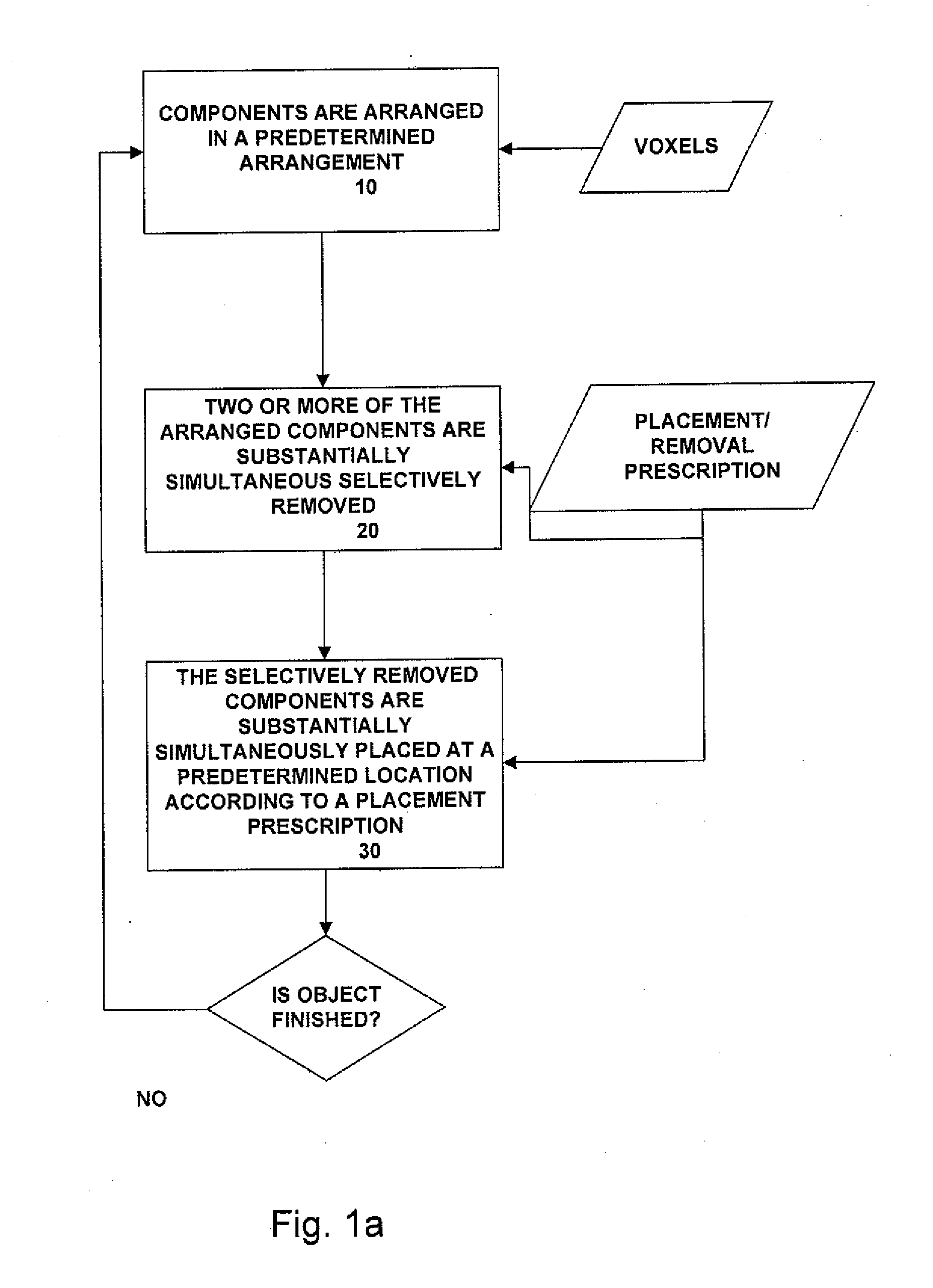
[0023]FIG. 1a shows a flowchart of one embodiment of the method of these teachings. Referring to FIG. 1a, components (voxels) are provided and the components are arranged in a predetermined arrangement at a predetermined area (step 10). Two or more of the arranged components are selectively removed, the removal occurring substantially simultaneously and according to a predetermined removal prescription (step 20). The selectively removed components are substantially simultaneously placed at predetermined locations according to a predetermined placement prescription (step 30). If the object / material has not been completed, steps 10 through 30 are repeated.

[0024]When the removal / placement prescription requires removing / placing only one component, only one component i...


PUM

PropertyMeasurementUnit
Forceaaaaaaaaaa
Electric chargeaaaaaaaaaa
Areaaaaaaaaaaa

Abstract

A method for manufacturing objects/materials includes selectively arranging the predetermined components in a staging area, substantially simultaneously selectively removing two or more of the selectively arranged predetermined components according to a predetermined removal plan and substantially simultaneously placing the selectively removed components, the removed components being substantially simultaneously placed at a predetermined location. A system for practicing the method includes a supply of the predetermined components, an arranging subsystem receiving the predetermined components and arranging the predetermined components according to a predetermined arrangement, a selective removal subsystem for selectively removing at least two of the selectively arranged predetermined components, the selectively removing occurring substantially simultaneously and according to a predetermined removal prescription, and a placement subsystem for substantially simultaneously placing the selectively removed components at a predetermined location.

Description

BACKGROUND[0001]These teachings relate generally to manufacturing objects / materials, and, more particularly, to digital manufacturing.[0002]Most conventional manufacturing techniques can be considered analog since the conventional manufacturing techniques are practically continuous, their substructure cannot be arbitrarily specified and accuracies lost with each measurement and subsequent application.[0003]Conventional three-dimensional printing processes are generally material-dependent and irreversible. Typically, conventional three-dimensional digital printers use continuous materials, with the digital specification being imposed by external logic. Conventional 3-dimensional fabrication is either additive or subtractive. Additive conventional three-dimensional printers work by depositing and / or bonding amorphous materials together in a way that results in a three-dimensional structure. Subtractive three-dimensional fabrication, such as with lathes or CNC milling machines, works b...

Claims


Application Information

Patent Timeline
IPC IPC(8): B32B5/00B23P11/00B32B38/14B32B38/10B32B38/18B05C5/00B05C9/12
CPCB29C67/0059Y10T156/17Y10T29/49826B29C64/112Y10T428/249921
Inventor HILLER, JONATHAN D.LIPSON, HOD
Owner CORNELL UNIVERSITY
Why Eureka
Try Eureka