
Method of providing 3D image and 3D display apparatus using the same

a technology of display apparatus and three-dimensional image, which is applied in the field of three-dimensional (3d) image and 3d display apparatus, can solve the problems of changing the timing of outputting left- and right-eye images, the general viewer would not be able to understand the format of 3d images, and the shutter glasses type apparatus, etc., so as to improve the accuracy of the display effect, the effect of changing the setting and easy checking

Inactive Publication Date: 2011-05-26
SAMSUNG ELECTRONICS CO LTD
View PDF31 Cites 37 Cited by
  • Summary
  • Abstract
  • Description
  • Claims
  • Application Information

AI Technical Summary

Benefits of technology

[0016]Exemplary embodiments also provide a method of providing a graphic user interface (GUI) regarding a 3D image, enabling a viewer to change setting items related to the 3D image more easily and conveniently, and a display apparatus using the same.
[0017]Exemplary embodiments also provide a method of displaying a 3D image which enables a viewer to change setting items related to the 3D image more easily and conveniently, and a display apparatus using the same.
[0018]Exemplary embodiments also provide a method of providing a GUI, which enables a viewer to change a setting related to a 3D image more easily and conveniently, and a display apparatus and a 3D image providing system using the same.
[0019]Exemplary embodiments also provide a display apparatus and a method of providing a 3D image which allows a viewer to more easily check if the timing of outputting a 3D image is synchronized with the timing of opening and closing shutter glasses.

Problems solved by technology

However, understanding a format of a 3D image would not be easy for the general viewers.
Further, the shutter glasses type apparatus often has problems such as change in the timing of outputting left- and right-eye images, or in the timing of opening and closing the eyeglasses.
One of the main drawbacks is that, due to the characteristic of a 3D image, a viewer does not immediately notice these changes in the timings while he watches the 3D image.
Also, exemplary embodiments are not required to overcome the disadvantages described above, and an exemplary embodiment may not overcome any of the problems described above.

Method used


Image

  • Method of providing 3D image and 3D display apparatus using the same
  • Method of providing 3D image and 3D display apparatus using the same
  • Method of providing 3D image and 3D display apparatus using the same

Examples


Embodiment Construction

[0114]Certain exemplary embodiments will now be described in greater detail with reference to the accompanying drawings.

[0115]In the following description, same drawing reference numerals are used for the same elements even in different drawings. The matters defined in the description, such as detailed construction and elements, are provided to assist in a comprehensive understanding of the invention. Accordingly, it is apparent that the exemplary embodiments can be carried out without those specifically defined matters. Also, well-known functions or constructions are not described in detail since they would obscure the exemplary embodiments with unnecessary detail.

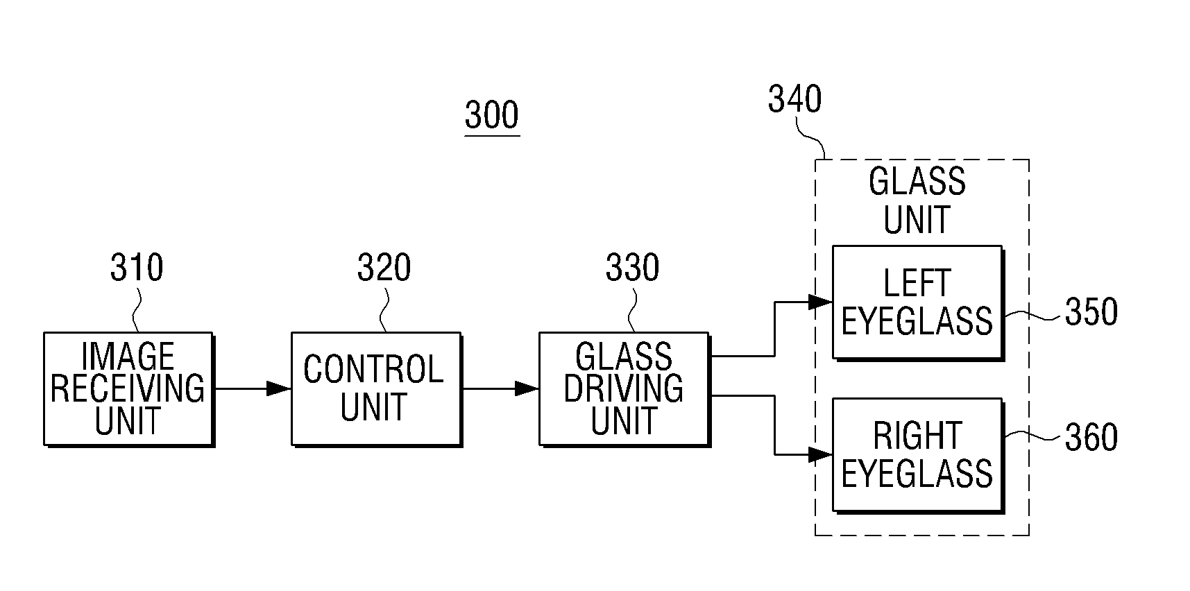
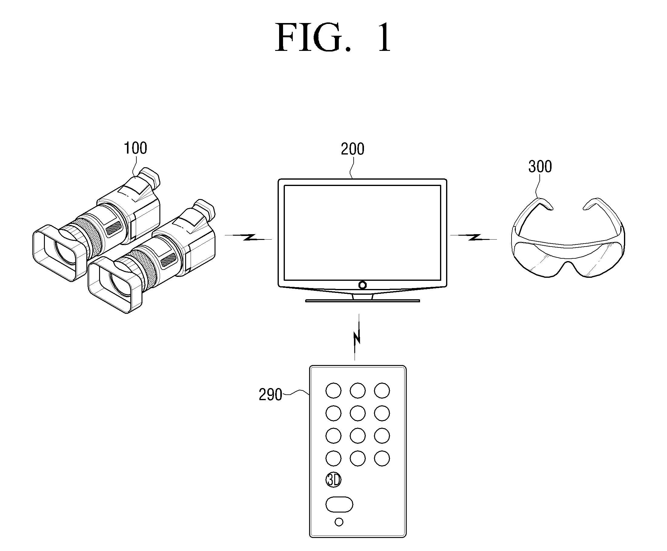
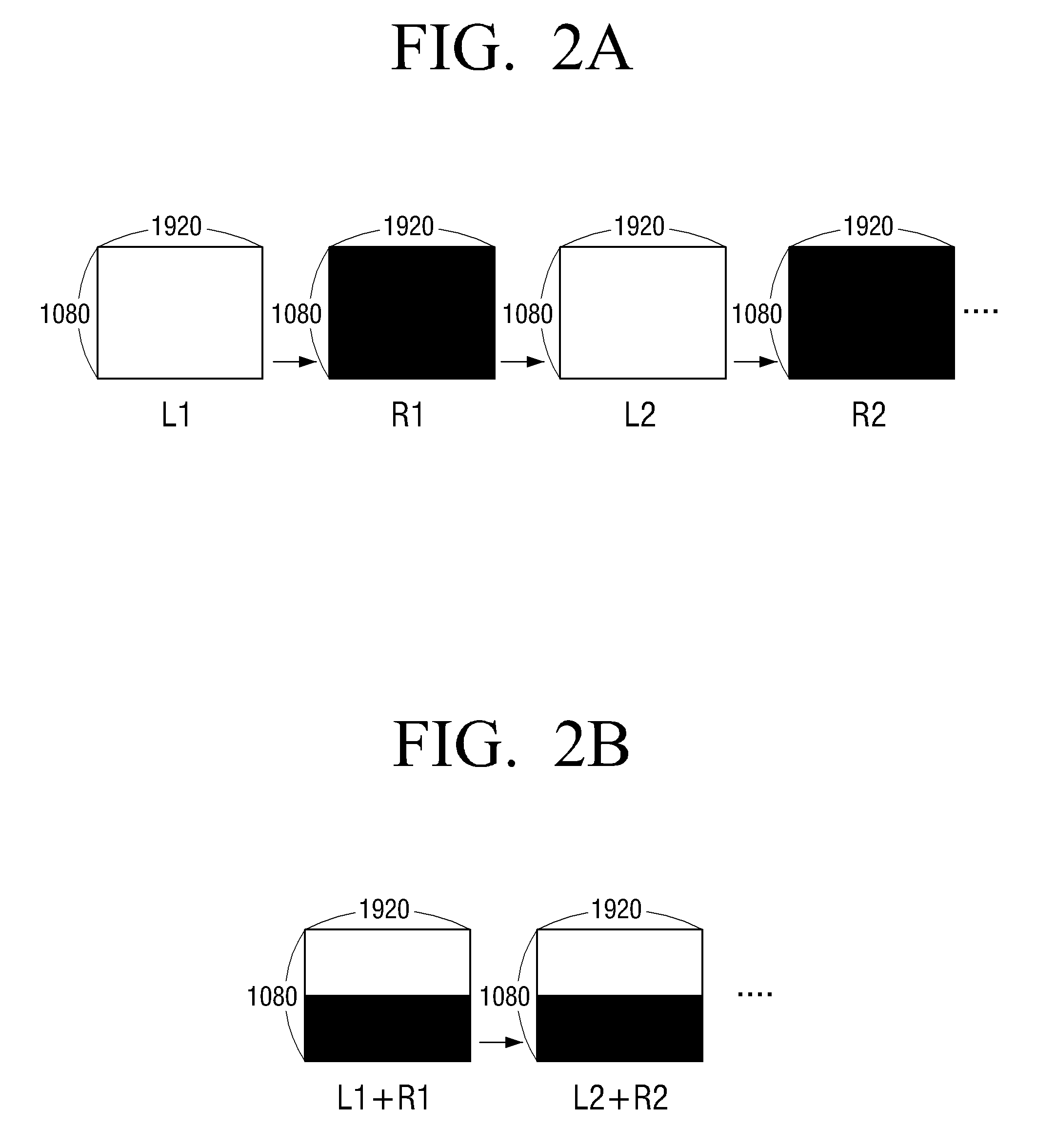
[0116]Hereinbelow, the principles of operation and construction of an exemplary system which provides a three-dimensional (3D) image will be described with reference to FIGS. 1 to 4. Processing a 3D image according to an exemplary embodiment will then be described with reference to FIGS. 5A to 5C. Also, the process of cha...


PUM


Abstract

A method of providing a three-dimensional (3D) image and a 3D display apparatus applying the same are provided. If a predetermined instruction is input in 2D mode, display mode is changed to 3D mode. A predetermined format is applied to an incoming image, and the resultant image is displayed in 3D mode. If the predetermined instruction is input again in 3D mode, another format is applied to the incoming image and the resultant image is displayed. As a result, a viewer can conveniently select a 3D image format of the incoming image.

Description

CROSS-REFERENCE TO RELATED APPLICATIONS[0001]This application claims priority from Korean Patent Application No. 10-2009-113197 filed on Nov. 23, 2009, Korean Patent Application No. 2009-113231 filed on Nov. 23, 2009, Korean Patent Application No. 2009-113224 filed on Nov. 23, 2009, Korean Patent Application No. 2009-113220 filed on Nov. 23, 2009, Korean Patent Application No. 2009-113234 filed on Nov. 23, 2009, Korean Patent Application No. 2009-114602 filed on Nov. 25, 2009, and Korean Patent Application No. 2009-114596 filed on Nov. 25, 2009, in the Korean Intellectual Property Office, the disclosures of which are incorporated herein by reference in their entirety.BACKGROUND OF THE INVENTION[0002]1. Field of the Invention[0003]Methods and apparatuses consistent with the exemplary embodiments relate to providing a three-dimensional (3D) image and a 3D display apparatus using the same, and more particularly, to providing a 3D image in which left-eye and right-eye images are display...

Claims


Application Information

Patent Timeline
IPC IPC(8): H04N13/04H04N13/00G06F3/048
CPCH04N13/0029H04N13/0048H04N13/007H04N13/0497H04N13/0454H04N13/0456H04N13/0438H04N13/139H04N13/161H04N13/183H04N13/341H04N13/359H04N13/361H04N13/398
Inventor HAN, JI-YOUNKO, CHANG-SEOG
Owner SAMSUNG ELECTRONICS CO LTD
Learn More