

Working machine control device, working machine, and working machine control method
a control device and working machine technology, applied in the direction of soil-shifting machines/dredgers, instruments, image data processing, etc., can solve problems such as abnormalities, and achieve the effect of changing settings and simple operation
- Summary
- Abstract
- Description
- Claims
- Application Information
AI Technical Summary
Benefits of technology
Problems solved by technology
Method used
Image

Examples
first embodiment
[0023]Hereinafter, a control device for a working machine according to a first embodiment will be described in detail with reference to FIGS. 1 to 11.
[0024](Structure of Working Machine)
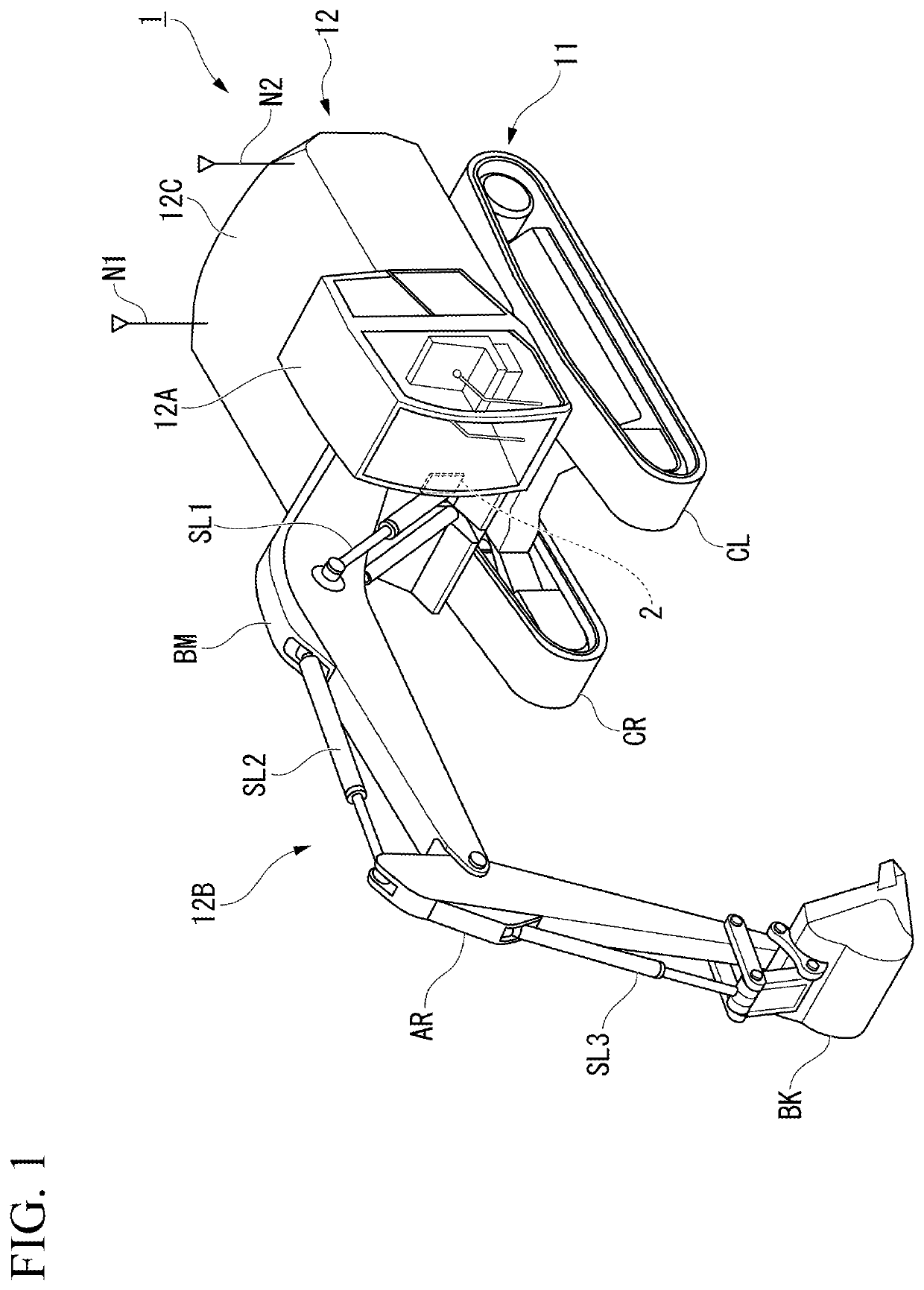
[0025]FIG. 1 is a diagram illustrating a structure of a working machine according to a first embodiment.
[0026]A working machine 1 that is a hydraulic excavator excavates and levels earth at a work site or the like.
[0027]As illustrated in FIG. 1, the working machine 1 that is a hydraulic excavator includes an undercarriage 11 for traveling and an upper swing body 12 that is provided on the undercarriage 11 and is able to swing. The upper swing body 12 is provided with a cab 12A, work equipment 12B, and two GNSS antennas N1 and N2.
[0028]The undercarriage 11 includes a left crawler CL and a right crawler CR. The working machine 1 moves forward, swings, and moves rearward with rotation of the left crawler CL and the right crawler CR.
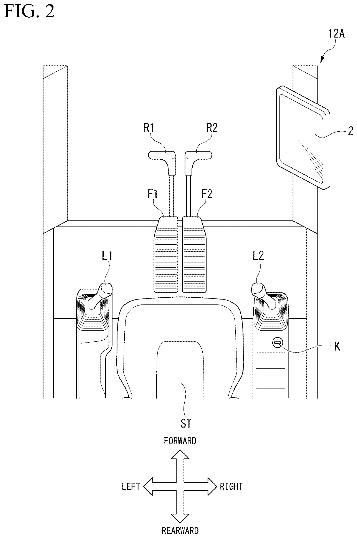
[0029]The cab 12A is a place where an operator of the working machine 1 ...
second embodiment
[0144]A control device according to a second embodiment will be described below in detail with reference to FIGS. 12 and 13.
[0145](Example of State Image)
[0146]FIG. 12 is a diagram illustrating an example of a state image according to the second embodiment.
[0147]A state image G illustrated in FIG. 12 is an image including various gauge images Gm1, Gm2, and Gm3 indicating an internal state of the working machine 1. Specifically, the gauge image Gm1 is a gauge image indicating an engine coolant temperature. The gauge image Gm2 is a gauge image indicating a hydraulic oil temperature. The gauge image Gm3 is a gauge image indicating an amount of remaining fuel. The state image G may be an image including at least one of the gauge images Gm1, Gm2, and Gm3. The gauge images may include another gauge image indicating the internal state of the working machine 1 such as a gauge image indicating a vehicle speed or a loading capacity.
[0148]When a touch on the state image G illustrated in FIG. 1...
modified examples
[0156]While the control devices 2 according to the first and second embodiments have been described above in detail, the specific configurations of the control device 2 are not limited to the above description and can be subjected to various changes in design without departing from the gist thereof.
[0157]For example, the control device 2 according to the first embodiment performs screen control on all the part images of the attachment image G101, the guidance image G4, the working machine model image G10, and the background image G0 by touching the corresponding part image, but another embodiment is not limited thereto.
[0158]That is, the control device 2 according to another embodiment may perform the aforementioned screen control on at least one of the attachment image G101, the guidance image G4, the working machine model image G10, and the background image G0.
[0159]The control devices 2 according to the first and second embodiments perform various types of screen control in respo...
PUM
 Abstract
Description
Claims
Application Information