Drive and tensioning unit for a scraper chain conveyor

Active Publication Date: 2011-06-09
CATERPILLAR INC
View PDF7 Cites 2 Cited by
  • Summary
  • Abstract
  • Description
  • Claims
  • Application Information

AI Technical Summary

Benefits of technology

[0005]In order to meet the above object, it is not absolutely necessary that the hydraulic cylinders, which generally can apply higher forces in the pressure direction than in the traction direction, can be supported against the machine frame without preferential direction. If the recesses in the side board are given a different configuration from the recesses in the side wall, then, correspondingly, differently configured connecting joint brackets can also be used. In a preferred embodiment, the recesses on the side board and the recesses on the side wall are identically constructed and also the connecting joint brackets for the two cylinder ends are identically constructed, so that only one connecting joint bracket and one shape of the recess has to be created to support both cylinders against the machine frame. At the same time, this embodiment minimizes the number of different components on a drive and tensioning unit. The recesses can be made directly in plate elements which form the side boards of the machine frame head or the side walls of the machine frame base. It is more advantageous if the recesses are an integral or constituent part of a bearing plate inserted in cavities or windows in the side wall and / or the side board, since this minimizes the production costs even where the geometry of the recess is complicated.
[0007]Further preferably, the locking piece can comprise a screwing means, which can either be screwed directly into the bearing bracket or can be fixed indirectly to the bearing bracket. The arrangement of the screwing means is preferably chosen such that this is not subjected to load by the forces acting upon the bearing bracket, but in principle secures the locking piece against falling out of the recess only by positive back-gripping action.
[0008]For a favourable support, as well as fitting and removal of the hydraulic cylinders, it is further advantageous if the bearing bracket has two bearing arms with bearing eyes, which bearing arms jut up over the base plate, and hence in the assembled state protrude laterally over the side wall or side board. According to a particularly advantageous embodiment, a bearing bolt can be insertable into the bearing eyes, which bearing bolt is secured against falling out by means of locking plates detachably anchored to one or both bearing arms. If a two-sided removal option is given for the locking plate, the hydraulic cylinder can then be removed, irrespective of its state of attachment on the left or right side of the machine frame, even when the bearing bracket is placed in the recess and is anchored there. At the same time, through removal of the bearing brackets on one side of the machine frame, a one-sided arrangement of a hydraulic cylinder can be achieved, without the presence of stop elements which project laterally beyond the free, cylinderless side board or side wall. In drum cutter-loader mining apparatus, the possibility is thereby afforded of arranging a hydraulic cylinder on one side only, preferably only on the stowage side, this to allow the mining machine, in particular the drum cutter-loader, to be transported, in principle, right into the machine frame base and thus take off the entire line of troughs of a scraper chain conveyor at constant distance from the working face.

Problems solved by technology

In order to utilize the drive and tensioning unit in mining installations as a face conveyor, particular problems in respect of hydraulic cylinders supported against the outer sides of the side boards or side walls consist in bridging the installation space necessary for these with the machine track.
In earlier applications of the Applicant, it has been proposed for this purpose to arrange the hydraulic cylinders inside the machine frame, whereby, however, the wear-induced or repair-induced removal of the hydraulic cylinders is made considerably more difficult.

Method used


Image

  • Drive and tensioning unit for a scraper chain conveyor
  • Drive and tensioning unit for a scraper chain conveyor
  • Drive and tensioning unit for a scraper chain conveyor

Examples


Embodiment Construction

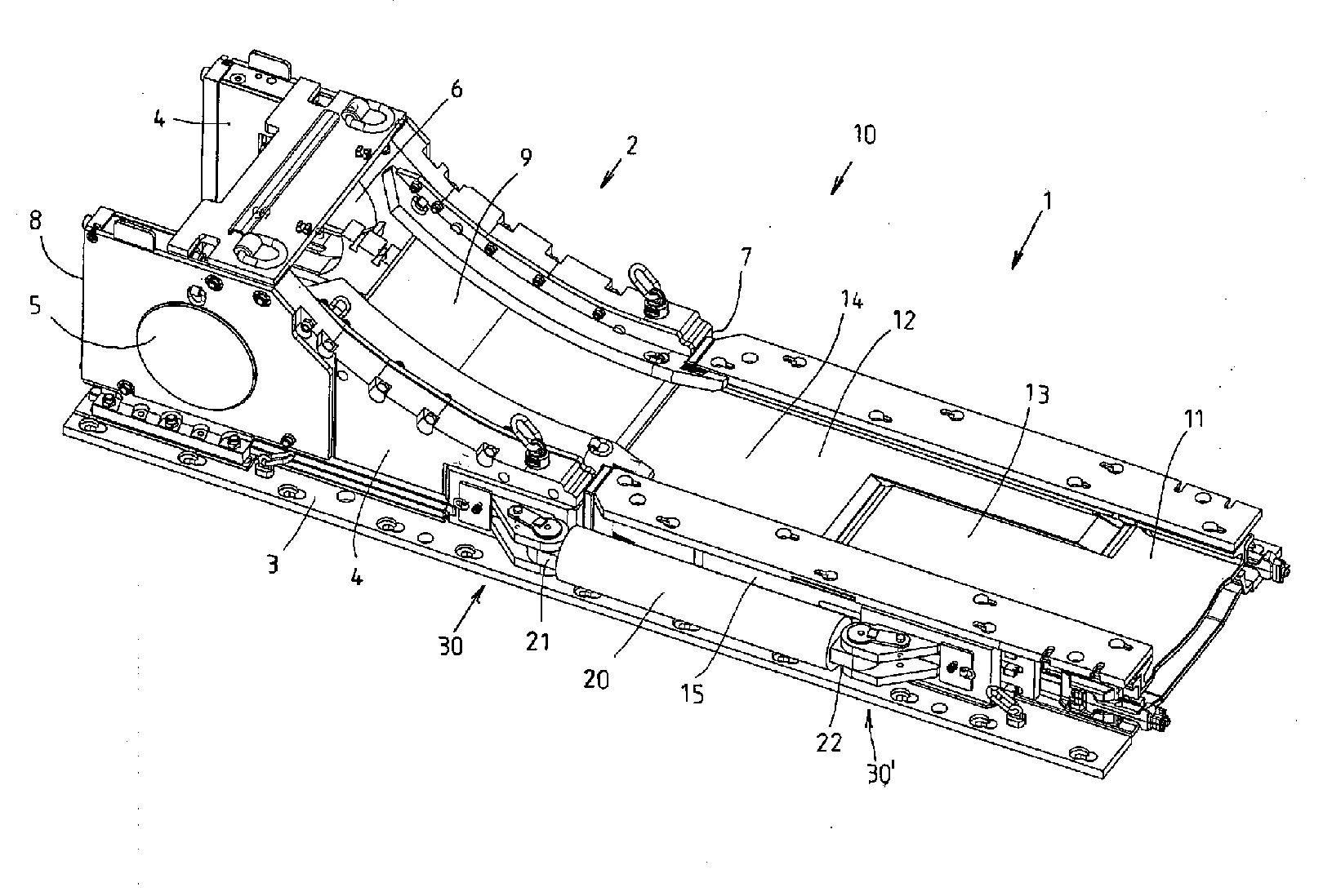
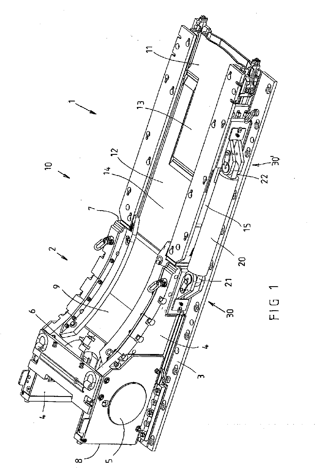
[0016]Referring now to the drawings wherein the showings are for the purpose of illustrating preferred and alternative embodiments of the invention only and not for the purpose of limiting same, FIG. 1 shows a drive and tensioning unit, denoted in its entirety by the reference symbol 10, which is attached to the head end of a scraper chain conveyor (not further represented), which is preferably used as a face conveyor in an underground mining operation. Since the structure and configuration of the non-represented scraper chain conveyor and also of the mining apparatus, formed preferably by a drum cutter-loader, are of no concern in this regard, no detailed description is here given of the scraper chain conveyor and / or of the mining apparatus. The drive unit 10 configured as a tensioning unit has a two-part machine frame comprising a machine frame base 1 and a machine frame head 2, which are here mounted on a common base plate 3. The machine frame head 2 has two lateral, strong side ...


PUM


Abstract

The invention relates to a drive and tensioning unit for a scraper chain conveyor, in particular a face conveyor for drum cutter-loader mining apparatus, comprising a telescopically configured machine frame (10) having a machine frame base and a machine frame head, which is displaceable relative to the machine frame base by means of at least one hydraulic cylinder (20) and has bearing recesses (6) for supporting a chain drum shaft, each hydraulic cylinder (20) being supported at one end in a connecting joint (30) on a side board (4) of the machine frame head (2) and at the other end in a connecting joint (30′) on a side wall (15) of the machine frame base (1). in order to improve the unit, the connecting joint (30) comprises a recess in the side board (4) an / or in the side wall (15) and a bearing bracket detachably anchorable in the recess (31), wherein structurally identical recesses are provided in both side boards (4) and in both side walls (15).

Description

[0001]The invention relates to a drive and tensioning unit for a scraper chain conveyor, in particular a face conveyor for drum cutter-loader mining apparatus, comprising a telescopically configured machine frame having a machine frame base, which is connectable to a line of troughs of the scraper chain conveyor, and a machine frame head, which is displaceable relative to the machine frame base by means of at least one hydraulic cylinder and has bearing recesses for supporting a chain drum shaft, each hydraulic cylinder being supported at one end in a connecting joint on a side board of the machine frame head and at the other end in a connecting joint on a side wall of the machine frame base.BACKGROUND OF THE INVENTION[0002]A drive and tensioning unit of the generic type is known from DE 100 50 701 B4. The known drive and tensioning unit has a hydraulic cylinder on both sides respectively and the scraper chain runs substantially horizontally through the machine frame both in the top...

Claims


Application Information

Patent Timeline
IPC IPC(8): B65G23/44B65G19/18
CPCB65G19/18B65G23/44B65G19/285
Inventor PLUSZYNSKI, ANDREASSCHURER, KARL-HEINZ
Owner CATERPILLAR INC
Why Eureka
Try Eureka