
Folding ultrasonic borehole imaging tool

a technology of ultrasonic and borehole, which is applied in the field of downhole tools, can solve the problems of mechanical wear, corrosion of the casing inside and outside, and wear of the casing from within

Active Publication Date: 2011-06-16
BAKER HUGHES OILFIELD OPERATIONS LLC
View PDF21 Cites 47 Cited by
  • Summary
  • Abstract
  • Description
  • Claims
  • Application Information

AI Technical Summary

Benefits of technology

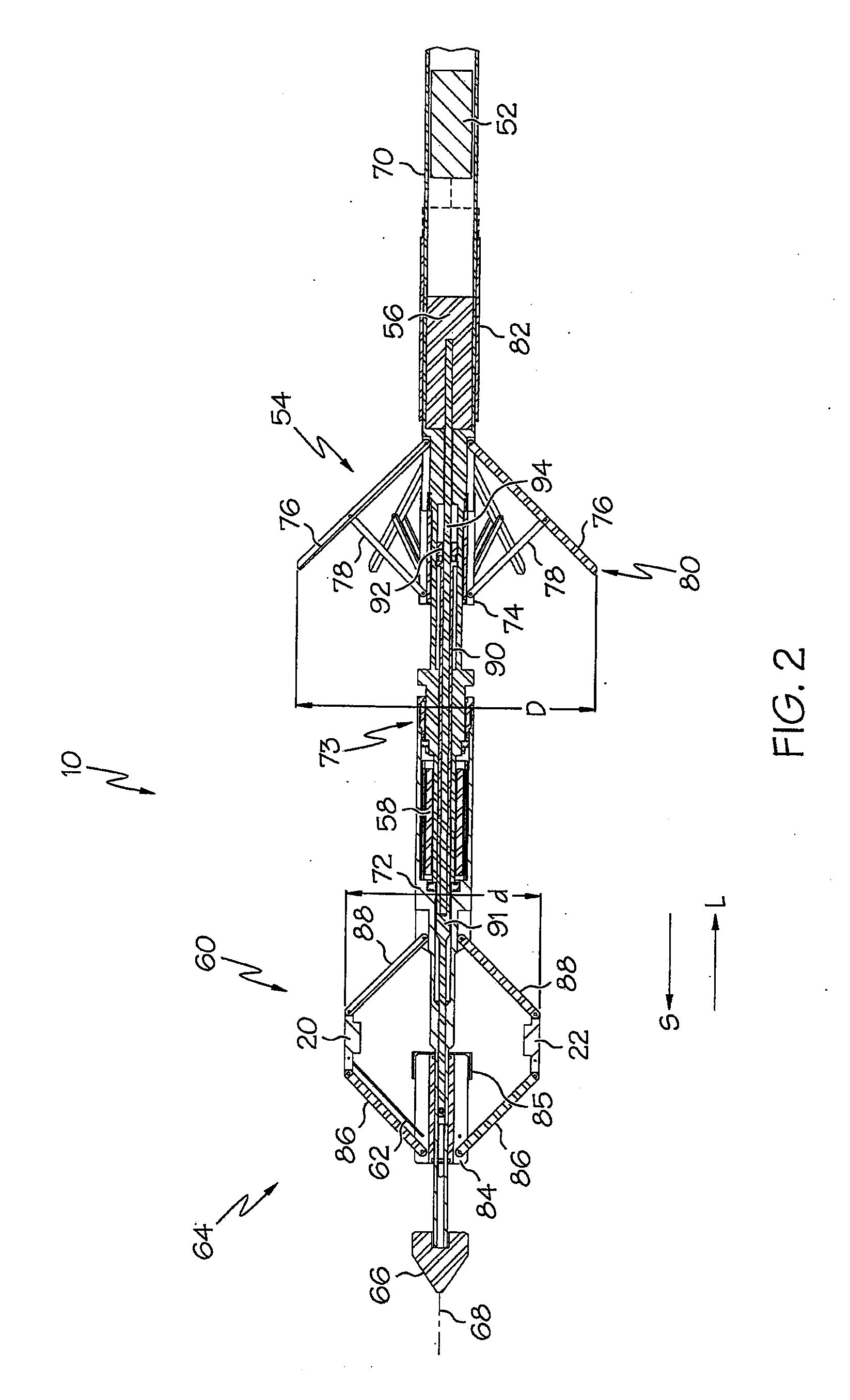
[0010]One aspect of the invention provides a borehole logging tool, including a housing oriented along a longitudinal axis and a centralizer assembly that positions the housing substantially at the center of the borehole. The centralizer assembly includes a first slider member and a plurality of centralizer arms coupled thereto. The first slider member is slidable along the longitudinal axis to selectively control a radial extension of the plurality of centralizer arms. The borehole logging tool further includes a scanning head that rotates a plurality of scanning sensors axially within the borehole about the longitudinal axis, and further includes a second slider member and a plurality of linkage arms coupling the second slider member to the plurality of scanning sensors. The second slider member is slidable along the longitudinal axis to selectively control a radial extension of the plurality of sensors.
[0011]Another aspect of the invention provides a borehole logging tool, including a housing oriented along a longitudinal axis, and a centralizer assembly that positions the housing substantially at the center of the borehole. The centralizer assembly includes a plurality of centralizer arms radially extendable outward from the longitudinal axis at a first diameter. The borehole logging tool further includes a scanning head that rotates a plurality of scanning sensors axially within the borehole about the longitudinal axis. The scanning head further includes a plurality of linkage arms coupled to the plurality of scanning sensors such that the scanning sensors are radially extendable outward from the longitudinal axis at a second diameter. The borehole logging tool further includes an extension assembly adapted to substantially concurrently control the radial extension of the centralizer arms and the plurality of sensors.
[0012]Another aspect of the invention provides a borehole logging tool, including a centralizer assembly that positions a housing substantially at the center of the borehole, and further including a first slider member and a plurality of centralizer arms coupled thereto. The first slider member is slidable along a longitudinal axis to selectively control a radial extension of the plurality of centralizer arms. The borehole logging tool further includes a scanning head that rotates a plurality of scanning sensors axially within the borehole about the longitudinal axis. The scanning head further includes a second slider member coupled to the plurality of scanning sensors, the second slider member being slidable along the longitudinal axis to selectively control a radial extension of the plurality of sensors. The borehole logging tool further includes a main shaft coupled to both of the first and second slider members and linearly movable along the longitudinal axis to drive sliding movement of both of the first and second slider members to simultaneously control the radial extension of the centralizer arms and the plurality of sensors.

Problems solved by technology

Corrosion can occur both inside and outside of the casing.
Mechanical wear from pump rods and the like can wear the casing from within.
In addition or alternatively, various grouting problems can compromise hydraulic isolation of the casing, such as improper bonding, incomplete filling of the casing-cement annulus, and / or casing corrosion / wear.
Borehole environments are typically harsh in temperature, pressure and ruggosity, and can adversely affect the response of any logging system operating therein.
More specifically, measures of the borehole parameters can be adversely affected by harsh borehole conditions.

Method used


Image

  • Folding ultrasonic borehole imaging tool
  • Folding ultrasonic borehole imaging tool
  • Folding ultrasonic borehole imaging tool

Examples


Embodiment Construction

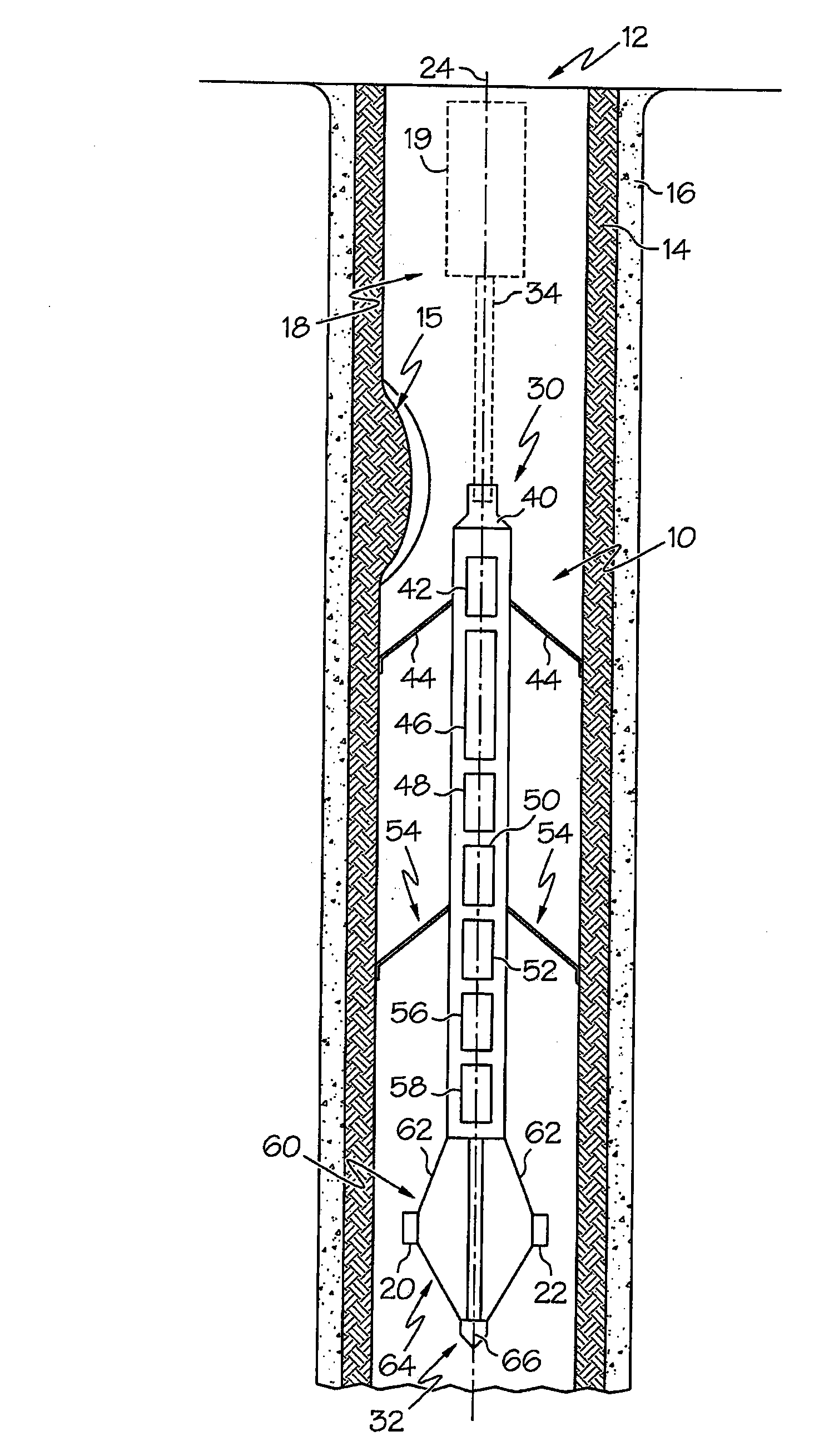
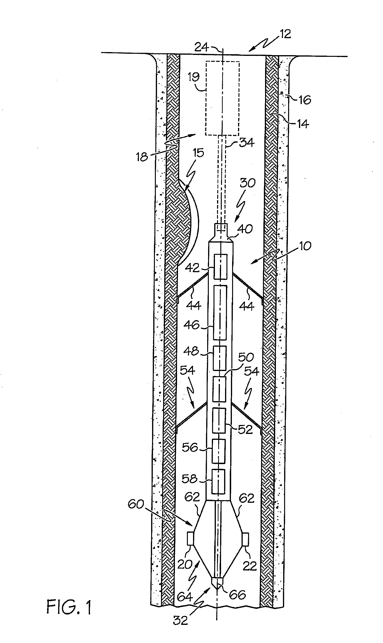
[0017]Example embodiments that incorporate one or more aspects of the invention are described and illustrated in the drawings. These illustrated examples are not intended to be a limitation on the invention. For example, one or more aspects of the invention can be utilized in other embodiments and even other types of devices. Moreover, certain terminology is used herein for convenience only and is not to be taken as a limitation on the invention. Still further, in the drawings, the same reference numerals are employed for designating the same elements.

[0018]For the purposes of this disclosure, the term “tool” is very generic and may be applied to any device sent downhole to perform any operation. Particularly, a downhole tool can be used to describe a variety of devices and implements to perform a measurement, service, or task, including, but not limited to, pipe recovery, formation evaluation, directional measurement, and / or workover.

[0019]Turning to FIG. 1, an example embodiment o...


PUM


Abstract

A borehole logging tool includes a housing oriented along a longitudinal axis, and a centralizer assembly that positions the housing substantially at the center of the borehole. In one example, the centralizer assembly includes a plurality of centralizer arms radially extendable outward from the longitudinal axis. The borehole logging tool further includes a scanning head that rotates a plurality of scanning sensors axially within the borehole about the longitudinal axis. The scanning head further includes a plurality of linkage arms coupled to the plurality of scanning sensors such that the scanning sensors are radially extendable outward from the longitudinal axis. The borehole logging tool further includes an extension assembly adapted to substantially concurrently control the radial extension of the centralizer arms and the plurality of sensors.

Description

BACKGROUND OF THE INVENTION[0001]1. Field of the Invention[0002]The invention relates to downhole tools, and specifically relates to a borehole logging tool operable over a range of borehole sizes.[0003]2. Discussion of Prior Art[0004]Well boreholes are typically drilled in earth formations to produce fluids from one or more of the penetrated formations. The fluids include water, and hydrocarbons such as oil and gas. Well boreholes are also drilled in earth formations to dispose waste fluids in selected formations penetrated by the borehole. The boreholes are typically lined with tubular structure commonly referred to as casing. Casing is typically steel, although other metals and composites such as fiberglass can be used. Grouting material, such as cement, fills the casing-borehole annulus to hydraulically isolate various formations penetrated by the borehole and casing.[0005]The wall of the casing can be thinned. Corrosion can occur both inside and outside of the casing. Mechanica...

Claims


Application Information

Patent Timeline
Patent Type & Authority Applications(United States)
IPC IPC(8): E21B47/00
CPCE21B47/0002E21B17/1021E21B47/002E21B47/0025
Inventor LARGE, STUART ANTHONYKENNEDY, SCOTT RONALDWOOD, RICHARD HARVEY
Owner BAKER HUGHES OILFIELD OPERATIONS LLC
Learn More