
High brightness light panel

a technology of high brightness and light, applied in the direction of identification means, lighting and heating apparatus, instruments, etc., can solve the problems of increasing the number, deteriorating the assemblability, and the conventional light panel, and achieve the effect of high brightness, high brightness, and high brightness

Inactive Publication Date: 2011-06-16
PARAENT
View PDF3 Cites 0 Cited by
  • Summary
  • Abstract
  • Description
  • Claims
  • Application Information

AI Technical Summary

Benefits of technology

[0011]An aspect of exemplary embodiments of the present invention is to address at least the problems and / or disadvantages and to provide at least the advantages described below. Accordingly, an aspect of exemplary embodiments of the present invention is to realize a large-area light panel of a high definite and a high brightness using an External Electrode Fluorescent Lamp (EEFL) of a high brightness and a stable operation characteristic.
[0012]Another aspect of exemplary embodiments of the present invention is to provide an internal / external electrode holder of an excellent insulation characteristic, thereby removing a shadow spot as well as maintaining a uniform brightness throughout the light panel surface.
[0013]A further aspect of exemplary embodiments of the present invention is to modularize and group a plurality of EEFLs as a plurality of unit lamp groups through an integrated internal / external electrode holder connecting the plurality of EEFLs conductible with each other, thereby making installation and uninstallation easy.
[0014]A still another aspect of exemplary embodiments of the present invention is to install a heat sink, thereby preventing a safety accident resulting from a high heat or a high voltage, preventing a work failure, and improving product reliability.

Problems solved by technology

However, the conventional light panel has the problems as follows.
The first is that, because the plurality of lamp holders are combined with the light emitting units to hold one EEFL, assemblability is deteriorated due to an increase of the number of parts, and the lamp holder interrupts light emission of the light emitting unit.
The second is that, because individual sockets are each combined with the external electrodes of the respective EEFLs and these sockets are connected through the power line, installation and uninstallation of the EEFL is difficult, and the extensibility for large-sizing of the light panel is remarkably deteriorated.
The third is that, because of an increase of manhour of each EEFL, workability decreases as well as a manufacturing cost increases.

Method used


Image

  • High brightness light panel
  • High brightness light panel
  • High brightness light panel

Examples


Embodiment Construction

[0029]Exemplary embodiments of the present invention will now be described in detail with reference to the annexed drawings. In the following description, a detailed description of known functions and configurations incorporated herein has been omitted for conciseness.

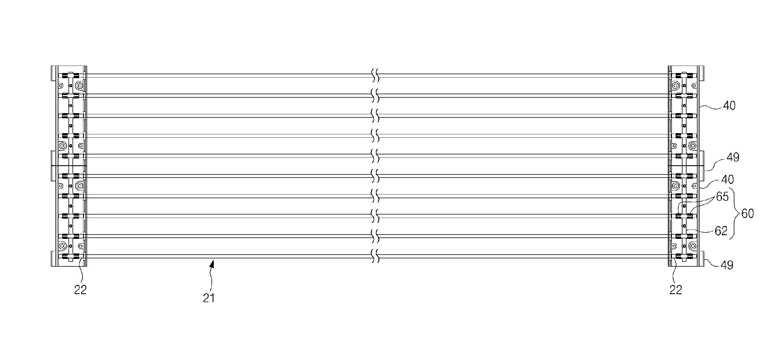
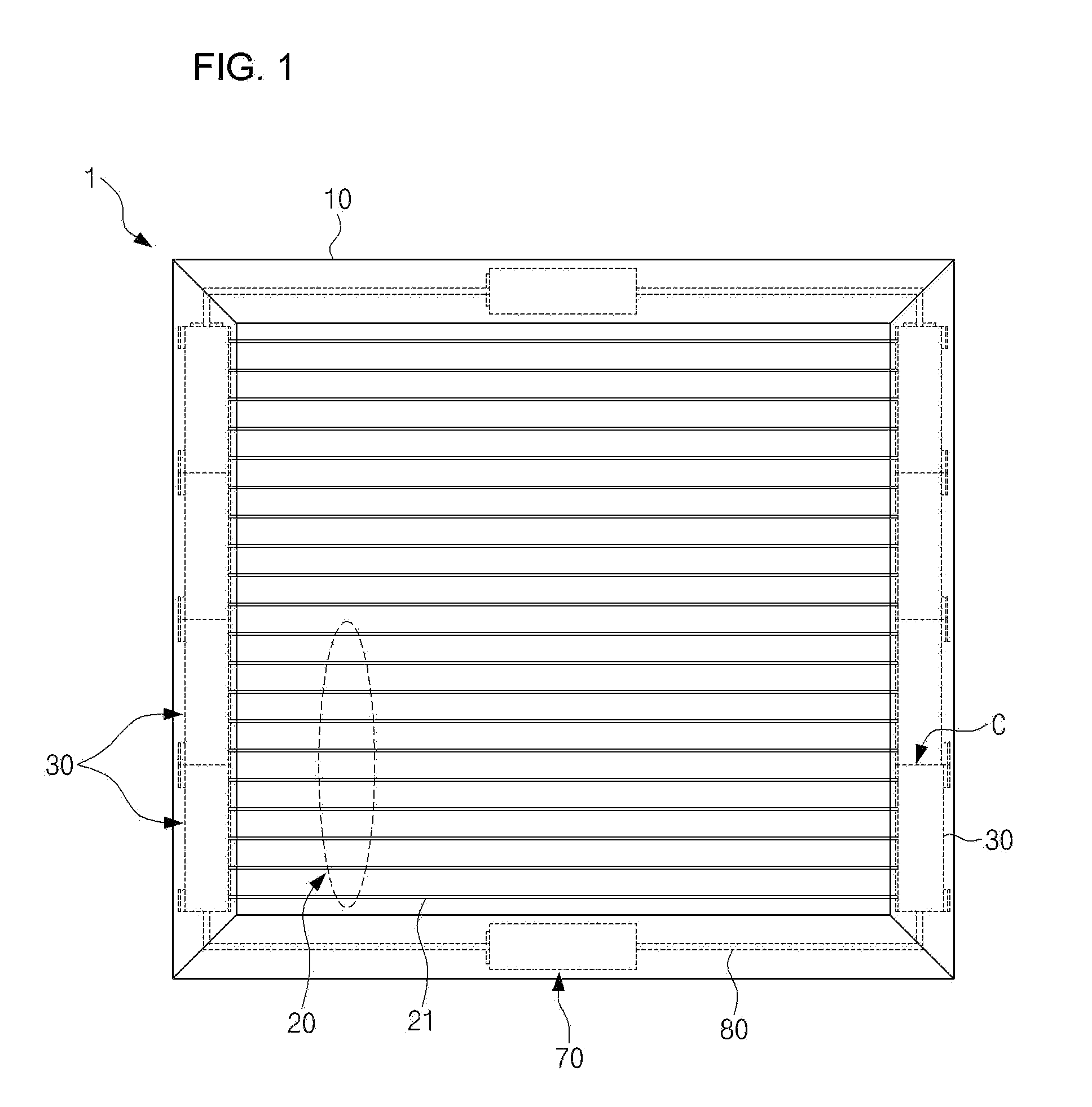
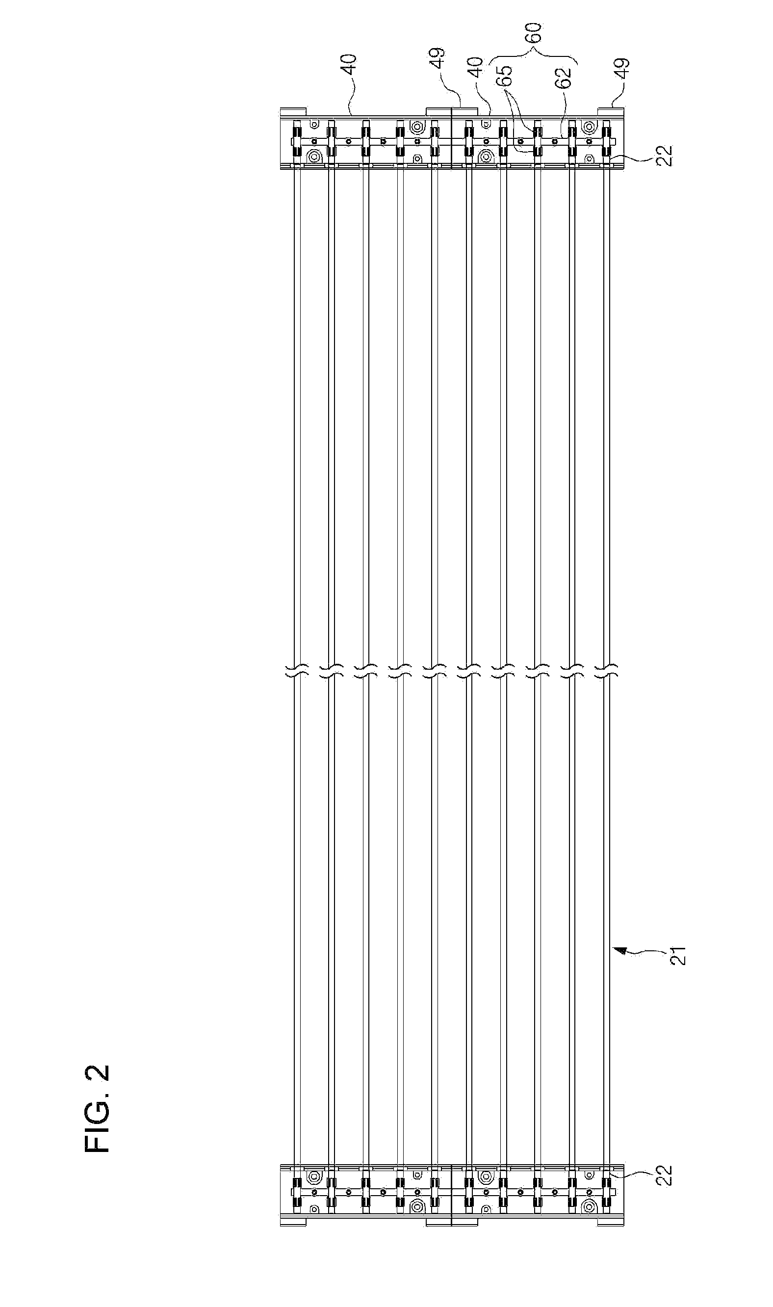
[0030]FIG. 1 is a plane diagram illustrating a high brightness light panel according to an exemplary embodiment of the present invention. FIG. 2 is a schematic plane diagram illustrating a lighting unit of the light panel according to the present invention.

[0031]As illustrated, the light panel 1 of the present invention includes a fixing frame 10, a light reflective plate 5 (shown in FIG. 4), a lighting unit 20, and an external electrode holder 30.

[0032]The fixing frame 10, a rectangular outer frame formed for billboard (not shown) installation, can be variously formed according to a size and shape of a billboard. A plurality of frames are formed inside the fixing frame 10 such that the light reflective plate 5, a cove...


PUM


Abstract

A high brightness light panel is provided. The light panel includes a fixing frame, a light reflective plate, a lighting unit, and an external electrode holder. The fixing frame forms an outer frame. The light reflective plate is installed in the fixing frame. The lighting unit has at least one or more External Electrode Fluorescent Lamps (EEFLs) spaced apart and arranged in parallel and forming one unit lamp group. The external electrode holder is sliding-inserted and installed along a length direction of the fixing frame, and has sockets installed therein and fixing-supporting external electrodes of the EEFLs.

Description

CROSS REFERENCE[0001]This application claims foreign priority under Paris Convention and 35 U.S.C. §119 to Korean Patent Application Nos. 10-2009-0122573 filed Dec. 10, 2009, 10-2009-0122576 filed Dec. 10, 2009, and 10-2009-0122576 filed Dec. 10, 2009, respectively with the Korean Intellectual Property Office.BACKGROUND OF THE INVENTION[0002]1. Field of the Invention[0003]The present invention relates to a high brightness light panel. More particularly, the present invention relates to a high brightness light panel for providing a unit lamp group in which a plurality of External Electrode Fluorescent Lamps (EEFLs) are spaced apart and arranged in parallel and also connecting a plurality of the unit lamp groups without a shadow spot, thereby not only being capable of modularizing EEFLs of a high brightness and a stable operation characteristic and easily realizing a large-size light panel but also being capable of improving product reliability through uniform brightness security.[000...

Claims


Application Information

Patent Timeline
Patent Type & Authority Applications(United States)
IPC IPC(8): F21V7/04F21V29/00F21V29/505
CPCG02F1/133604G02F1/133608G02F2001/133612H01J5/60G09F13/26H01J5/48G09F9/35G02F1/133612
Inventor JEON, KIHYUNHAN, KIWONCHOE, CHEOLYONG
Owner PARAENT
Learn More