Lens driving device

Inactive Publication Date: 2008-04-10
SAMSUNG ELECTRO MECHANICS CO LTD
View PDF5 Cites 11 Cited by
  • Summary
  • Abstract
  • Description
  • Claims
  • Application Information

AI Technical Summary

Benefits of technology

[0013] An aspect of the present invention provides a lens driving device which, during frictional driving, generates a sufficient friction force necessary for driving a lens, with p

Problems solved by technology

However, when the vibrator runs for long time, the friction force between the guide shaft and the driving contacting part causes the driving contacting part having a very rough surface to be abraded even though the driving c

Method used


Image

  • Lens driving device
  • Lens driving device
  • Lens driving device

Examples


example

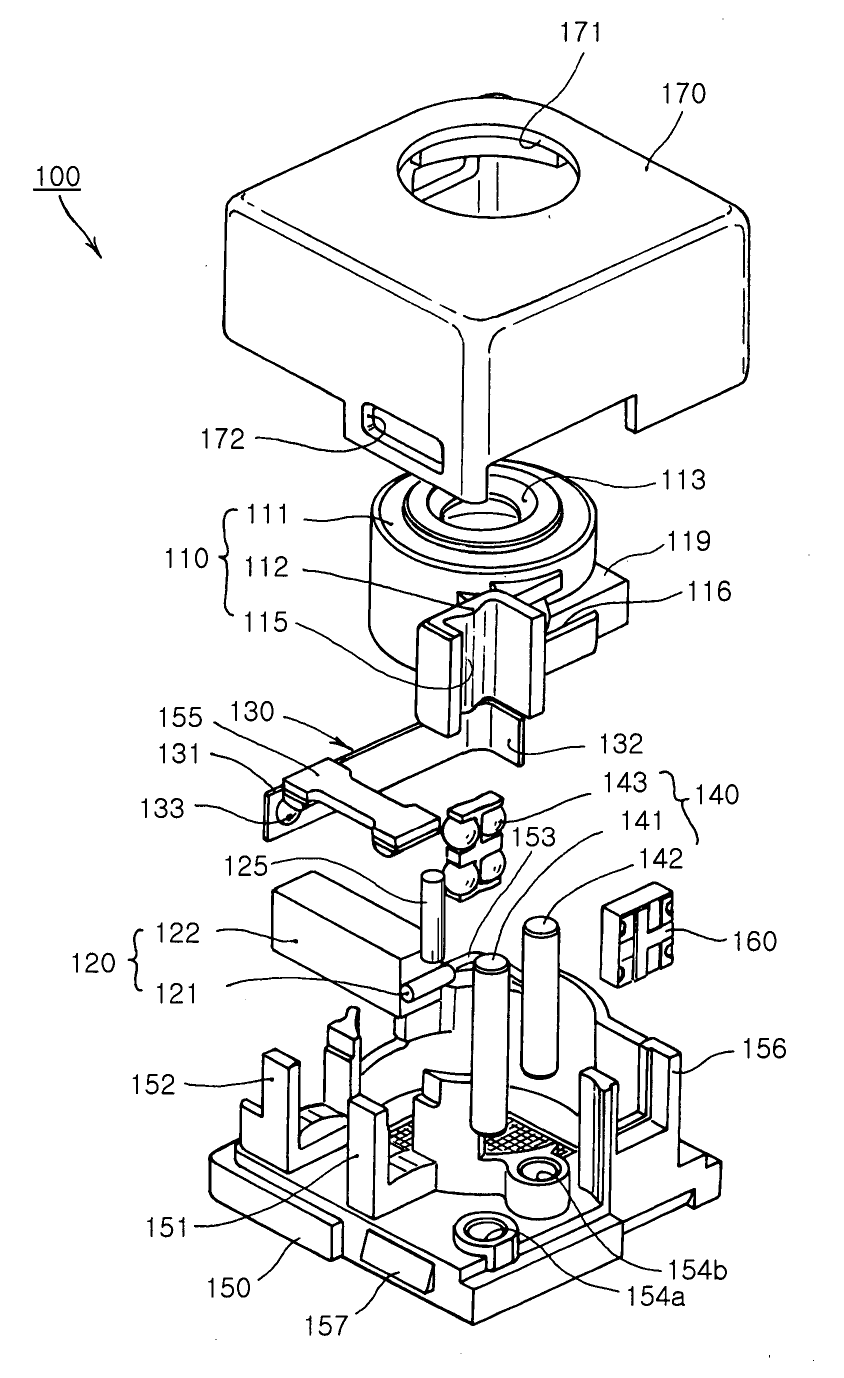
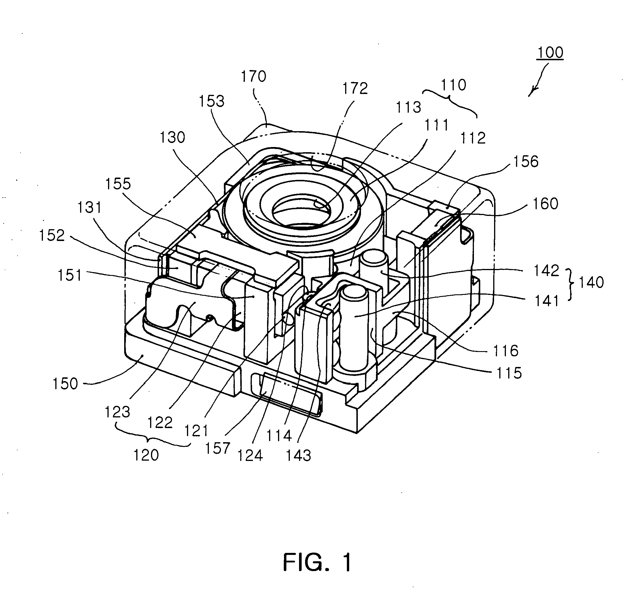
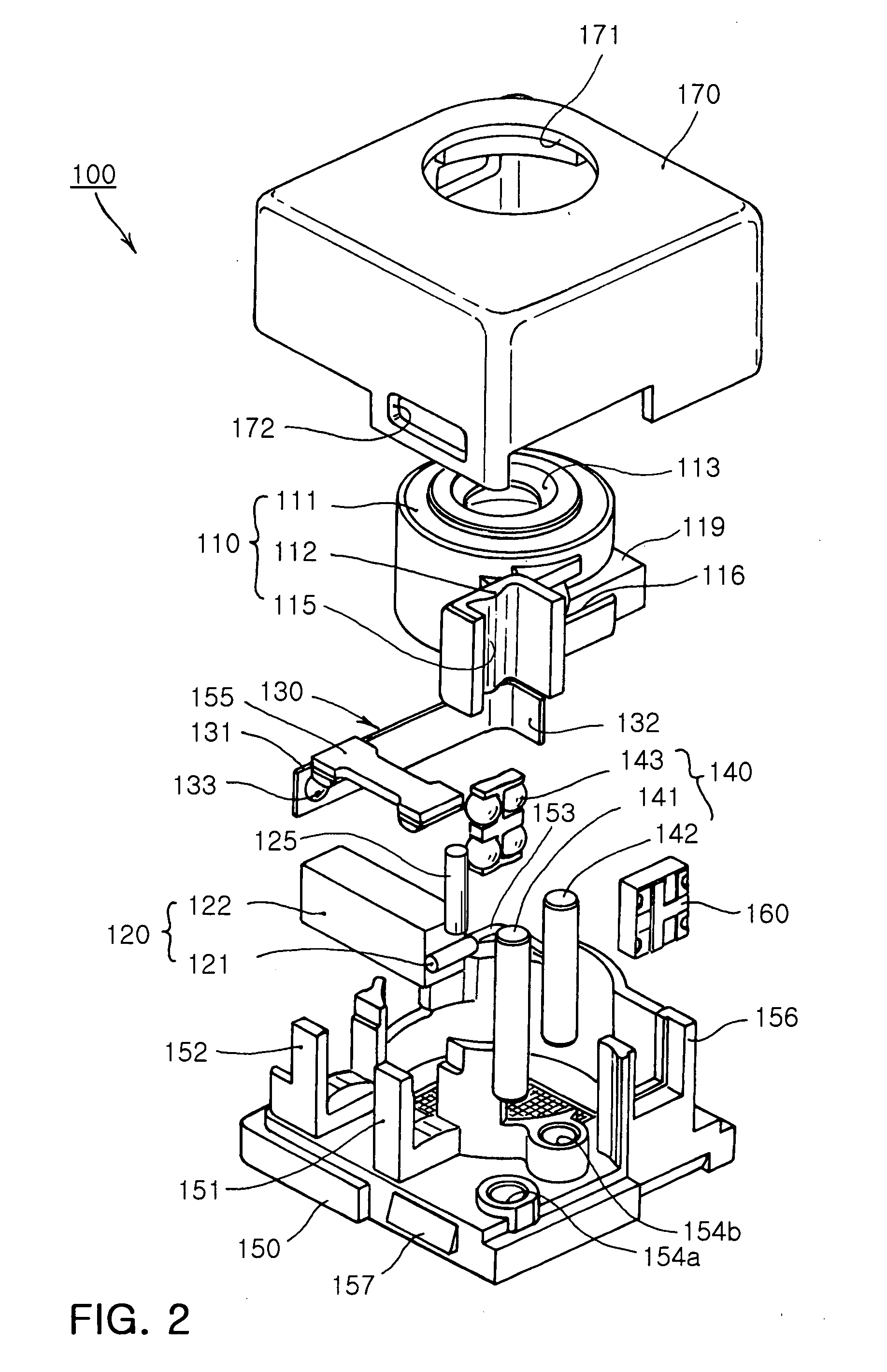
[0084] Table 2 below shows results after repeatedly operating an actuator 300,000 times, which employed the tip friction member 121 and the friction member 125 formed of high-strength friction materials of Table 1.

TABLE 1FractureFrictionDensityHardnessstrengthTensilematerial(kg / mm3)(HK)(GPa)forceRemarkSiC32002480 kg / mm20.18620.03448˜0.1379Al2O340002100 kg / mm20.9034 0.2552˜0.2607Super-hard alloy158001875 kg / mm20.3838˜0.57930.3448High speed steel1250 kg / mm20.44000.3800Corrosion

[0085]

TABLE 2Tip frictionFrictionComparison (after 300,000membermemberfrictional operations)1Al2O3Al2O3Degraded performance2Al2O3High-speedExcessive abrasion, greatsteel (SKH)amount of dusts, noises3SiCHigh-speedExcessive abrasion, greatsteel (SKH)amount of dusts4Super-Super-Good performance, smallhardnesshardnessamount of dustsalloy(WC)steel (SKH)5Super-Super-Good performance, smallhardnesshardnessamount of dustsalloy(WC)alloy (WC)

[0086] As noted in Table 2, when the tip friction member 121 and the friction m...


PUM


Abstract

A lens driving device including: a lens barrel having at least one lens therein; an actuator having a tip friction member provided at a leading end of a body thereof to be in contact with a friction member of the lens barrel, the actuator being flexed and bent upon application of power to provide a driving force necessary for driving the lens barrel in an optical axis direction; a preload member compressing the actuator against the lens barrel to keep the friction member and the tip friction member in contact with each other; and a guiding part guiding the lens barrel to move in the optical axis direction, wherein the friction member and the tip friction member are formed of a super-hard alloy.

Description

CROSS-REFERENCE TO RELATED APPLICATIONS [0001] This application claims the priority of Korean Patent Application No. 2006-94351 filed on Sep. 27, 2006, in the Korean Intellectual Property Office, the disclosure of which is incorporated herein by reference. BACKGROUND OF THE INVENTION [0002] 1. Field of the Invention [0003] The present invention relates to a lens driving device employed in an optical apparatus, more particularly, which, during frictional driving, generates a friction force necessary for driving a lens, with predetermined hardness maintained, but suffers minimal abrasion, thereby achieving stable operation properties and higher driving properties. [0004] 2. Description of the Related Art [0005] In general, an optical apparatus includes a lens driving device for driving a lens using a cam structure, a screw or a piezoelectric element. The lens driving device employs a motor or the piezoelectric element to generate a driving force and the cam structure or the screw to t...

Claims


Application Information

Patent Timeline
IPC IPC(8): G02B7/02
CPCG02B7/021G02B7/08H02N2/026H02N2/004H01L41/0913H10N30/2023G02B7/04G02B7/02
Inventor LEE, DONG KYUNKANG, BYUNG WOO
Owner SAMSUNG ELECTRO MECHANICS CO LTD
Why Eureka
Try Eureka