Method for actuating a braking system

A braking system and braking force technology, applied in the direction of braking safety systems, brakes, brake components, etc., to achieve the effect of improving driving characteristics

Active Publication Date: 2014-04-16
VOLKSWAGEN AG
View PDF8 Cites 6 Cited by
  • Summary
  • Abstract
  • Description
  • Claims
  • Application Information

AI Technical Summary

Problems solved by technology

But this prompt is usually limited to asking to find a professional repair shop

Method used


Image

  • Method for actuating a braking system

Examples


Embodiment Construction

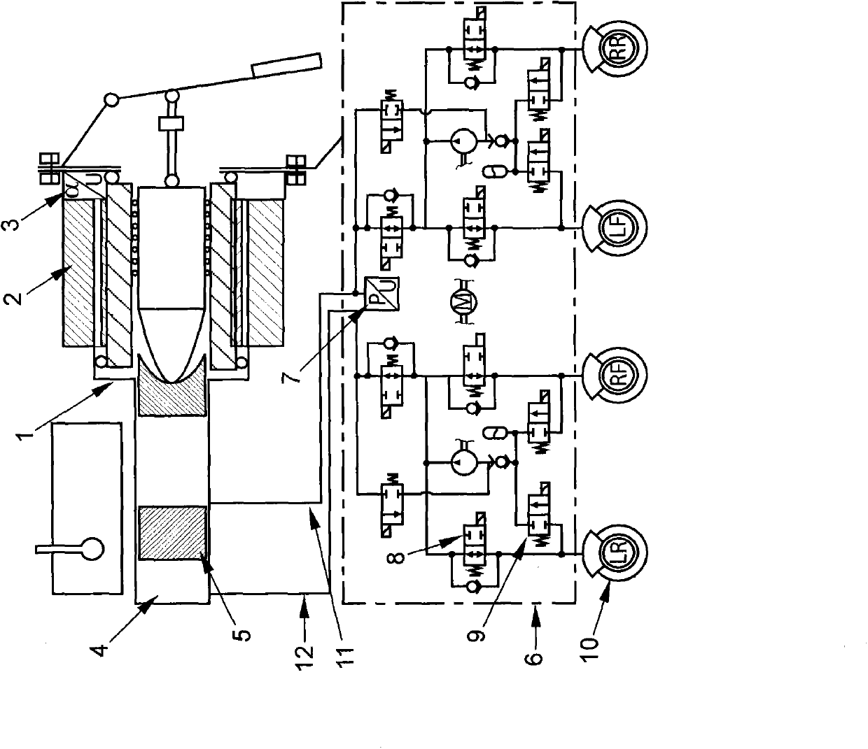
[0021] The braking system is equipped with an electric brake booster 1 having a commutator electric motor as drive 2 . In the exemplary embodiment shown, the drive mechanism 2 detects the corresponding adjustment position with an angle sensor 3 . The brake system also includes a slip control system 6 with a pressure sensor 7 with which the hydraulic pressure in one of the two brake circuits is detected. The two brake circuits are connected to each other via the floating piston 5 of the tandem master cylinder 4 . This makes the brake pressure equal in both brake circuits. In normal operating conditions, each adjustment position of the drive mechanism 2 is assigned a certain pressure in the brake circuit, so that this assignment is clearly indicated by the characteristic curve. During the test cycle, a certain drive torque is generated by correspondingly controlling the drive mechanism 2 , to which a certain pressure is assigned according to the characteristic curve. This dri...


PUM


Abstract

The invention relates to a method for actuating an automotive braking system which is provided with a brake booster (1). The method involves detecting the drive torque and/or setting position of a driving mechanism (2) of the brake booster (1) and generated pressure in a brake circuit of the brake system. The leakage in the brake loop is detected based on the stored values in a database. Inlet valves (8) of specific wheel brakes (10) are opened and the inlet valves (8) of other wheel brakes (10) are closed successively, so that the leakage is determined to exist in at least one wheel brake (10). The wheel brake ((10) is switched off during subsequent operation, particularly driving of the motor car.

Description

technical field [0001] The invention relates to a method for controlling a brake system of a motor vehicle equipped with a brake booster, wherein the drive torque and / or the adjustment position, in particular the angular position, of a drive mechanism of the brake booster is detected, and The resulting pressure in the brake circuit of the brake circuit can be inferred from a leak in the brake circuit by comparative observation, in particular taking into account the values ​​stored in the database. Background technique [0002] Such a brake system with an electromechanical brake booster is already known in practice and thus belongs to the state of the art through the published prior use. In addition to the braking request predetermined by the continuous mechanical connection, an auxiliary force is applied by the electric drive. [0003] Thus for example DE 10327553 A1 discloses an electromechanical brake booster comprising a piston rod for directly connecting the brake pedal...

Claims


Application Information

Patent Timeline
Patent Type & Authority Applications(China)
IPC IPC(8): B60T17/22B60T13/74
CPCB60T13/662B60T8/4872B60T17/221B60T8/88B60T8/40B60T8/90
Inventor B·维特
Owner VOLKSWAGEN AG
Why Eureka
Try Eureka