Optical Element driving device, optical element barrel, and image pickup apparatus

a driving device and optical element technology, applied in the direction of generator/motor, instruments, television systems, etc., can solve the problems of low precision of position detection and lack of detector for detecting the position of optical lenses, and achieve the effect of accurate detection

Inactive Publication Date: 2011-05-05
SONY CORP
View PDF7 Cites 7 Cited by
  • Summary
  • Abstract
  • Description
  • Claims
  • Application Information

AI Technical Summary

Benefits of technology

[0015]According to the embodiments of the present invention, the position of the optical element holder that is moved by the second piezoelectric element

Problems solved by technology

However, the existing lens drive technologies that use a piezoelectric element, such as the technologies described in Japanese Unexamined Patent Application Publication No. 2000-194026 and Japan

Method used


Image

  • Optical Element driving device, optical element barrel, and image pickup apparatus
  • Optical Element driving device, optical element barrel, and image pickup apparatus
  • Optical Element driving device, optical element barrel, and image pickup apparatus

Examples


first embodiment (

1. First Embodiment (an example structure of an optical element driving device)

second embodiment (

2. Second embodiment (another example structure of an optical element driving device)

Example of External View of Image Pickup Apparatus

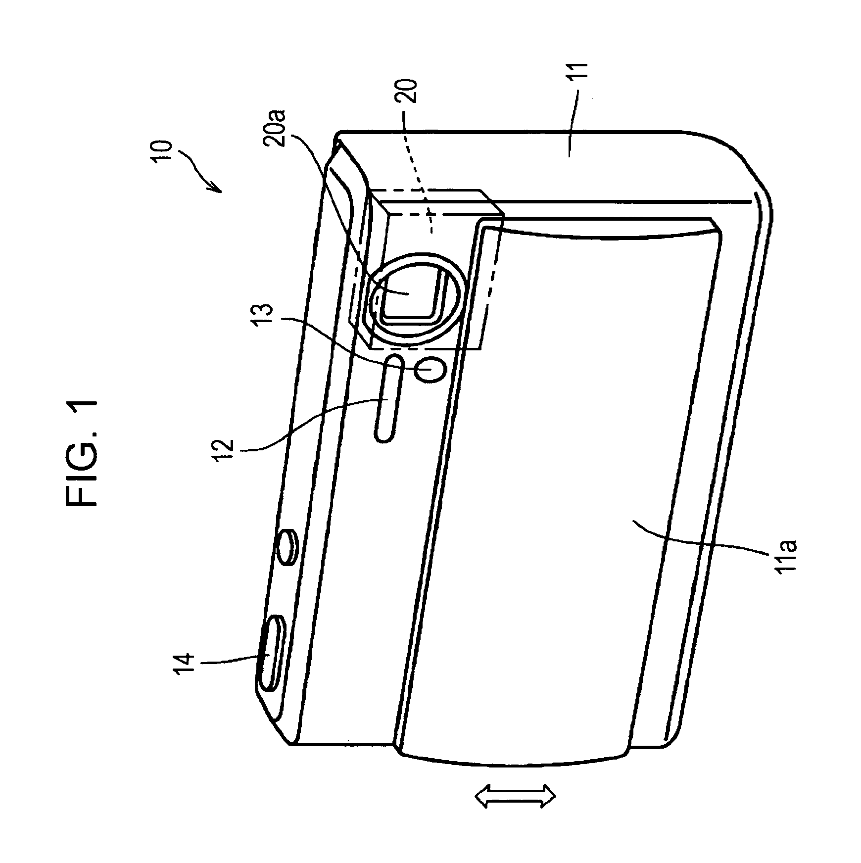
[0037]FIG. 1 is a perspective view of the front side of the digital still camera 10, which is an image pickup apparatus according to an embodiment of the present invention.

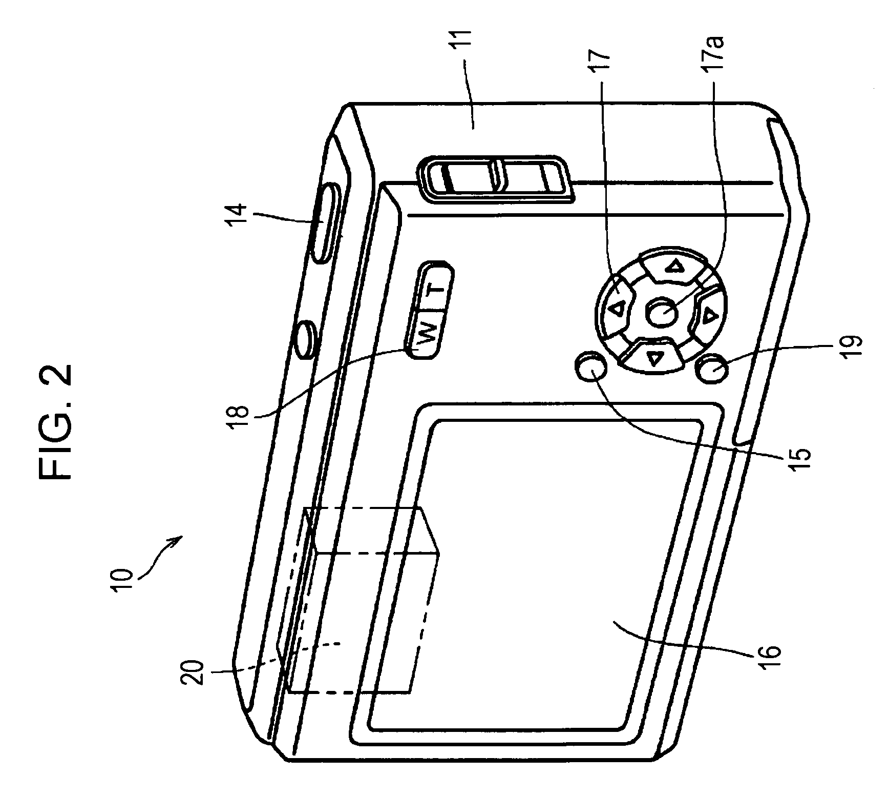
[0038]FIG. 2 is a perspective view of the rear side of the digital still camera 10, which is an image pickup apparatus according to an embodiment of the present invention.

[0039]As illustrated in FIG. 1, the digital still camera 10 includes a body 11, which is a rectangular-parallelepiped casing. As shown by a double-dotted chain line in FIG. 1, the lens barrel 20 (corresponding to an optical element barrel) is installed in an upper right part of the body 11. A lens 20a is disposed in a barrel body of the lens barrel 20 so that the lens 20a is positioned in an upper front part of the body 11.

[0040]Regarding the digital still camera 10 illustrated in FIGS. 1 and 2, left and right dir...

first embodiment

1. First Embodiment

Example Structure of Optical Element Driving Unit of Optical Element Barrel

[0043]FIG. 3 is a front view of an optical element driving unit 120 of a lens barrel, which is an optical element barrel according to an embodiment (first embodiment) of the present invention.

[0044]FIG. 4 is a cross-sectional view of the optical element driving unit illustrated in FIG. 3, taken along line IV-IV.

[0045]The optical element driving unit 120 illustrated in FIG. 3 is an optical element driving device that serves as a motion blur correction mechanism using a lens shift method in the digital still camera 10 illustrated in FIGS. 1 and 2. To be specific, a lens 21 for motion blur correction, which is an optical element, is moved in two directions perpendicular to the optical axis, whereby degradation of an image due to motion blur can be prevented.

[0046]In addition to the motion blur correction mechanism using the lens shift method, the optical element driving unit 120 is applicable ...


PUM


Abstract

An optical element driving device includes an optical element holder, first and second magnets, first and second magnetic bodies each having a cross section including a vertex and first and second legs forming an opening therebetween, first and second piezoelectric elements that move the optical element holder in directions perpendicular to each other by slidingly moving the first and second magnetic bodies by vibrating the first and second magnets, and first and second magnetic sensors that detect a position of the optical element holder, wherein the first and second piezoelectric elements are driven in a state in which the first and second magnets are coupled to the first and second legs from the opening side, wherein the first and second magnets are each magnetized in directions perpendicular to a magnetization line, and wherein the second magnetic sensor is disposed at a position that is not on the magnetization line.

Description

BACKGROUND OF THE INVENTION[0001]1. Field of the Invention[0002]The present invention relates to an optical element driving device that moves an optical element holder by slidingly moving a magnetic body by vibrating a magnet with a piezoelectric element. The present invention also relates to an optical element barrel and an image pickup apparatus including the optical element driving device.[0003]2. Description of the Related Art[0004]Image pickup apparatuses, such as digital still cameras, digital video cameras, and the like, focus an image of an object by using an image-taking optical lens (optical element). An image pickup device, such as a charge coupled device (CCD) image sensor or a complementary metal oxide semiconductor (CMOS) image sensor, is disposed to the rear of the optical lens, and the image pickup device forms the image of the object.[0005]In order to prevent degradation of an image due to shaking of such an image pickup apparatus, some digital still cameras and dig...

Claims


Application Information

Patent Timeline
IPC IPC(8): H04N5/225G02B7/04
CPCG02B7/08H02N2/007H04N5/2254H02N2/028H02N2/025H04N23/55
Inventor TAKEI, TOMOYA
Owner SONY CORP
Why Eureka
Try Eureka