
Trolley Wheel Technology

a technology of rollers and wheels, applied in the direction of cleaning using liquids, hoisting equipment, gearing, etc., can solve the problems of reducing the operational affecting the operation quality or life of the bearing assembly, and affecting the performance of the trolley

Active Publication Date: 2011-06-23
OCONOMOWOC MFG
View PDF26 Cites 15 Cited by
  • Summary
  • Abstract
  • Description
  • Claims
  • Application Information

AI Technical Summary

Benefits of technology

[0006]Some embodiments provide a method of washing a trolley wheel assembly of an overhead conveyor system. In the present method, the trolley wheel assembly comprises a wheel and an open bearing assembly. The wheel has a first face, a second face, and a rolling surface. At least one of the first and the second faces has a funnel configuration shaped to direct fluid toward the open bearing assembly for cleaning the open bearing assembly. The method comprises spraying fluid at the wheel face having the funnel configuration so as to direct the sprayed fluid into the open bearing assembly, thereby flushing the open bearing assembly with sprayed fluid. In some of the present embodiments, the wheel face having the funnel configuration has a plurality of channels extending from an outer edge region of the first face toward the open bearing assembly. Additionally or alternatively, the funnel configuration can optionally have a plurality of ribs extending toward the open bearing assembly. Preferably, the wheel face having the funnel configuration is angled axially inward from an outer edge region of that wheel face toward an inner boundary of that wheel face. In some of the present embodiments, each wheel face is angled axially inward from an outer edge region of the wheel face toward an inner boundary of the wheel face, such that sprayed fluid is directed into the open bearing assembly and fluid that thereby enters the bearing assembly can flow freely downwardly along either face of the wheel.

Problems solved by technology

During use, the trolley assemblies are subjected to a variety of environments in which the wheel assemblies can get dirty over a period of time.
Trolley performance can degrade as the bearing assemblies become dirty.
In many cases, debris and other contaminants within a bearing assembly can reduce the operational quality or life of the bearing assembly.
Such bearing assemblies, however, can be difficult to maintain, difficult to relubricate, and / or they may not operate as effectively as open bearings.
Moreover, when debris does enter such a bearing assembly, the debris can be extremely difficult to remove.

Method used


Image

  • Trolley Wheel Technology
  • Trolley Wheel Technology
  • Trolley Wheel Technology

Examples


Embodiment Construction

[0029]The following detailed description is exemplary in nature and is not intended to limit the scope, applicability, or configuration of the invention in any way. Rather, the following description provides some practical illustrations for implementing exemplary embodiments of the present invention. Examples of constructions, materials, dimensions, and manufacturing processes are provided for selected elements; all other elements employ that which is known to those of ordinary skill in the field of the invention. Those skilled in the art will recognize that many of the noted examples have a variety of suitable alternatives.

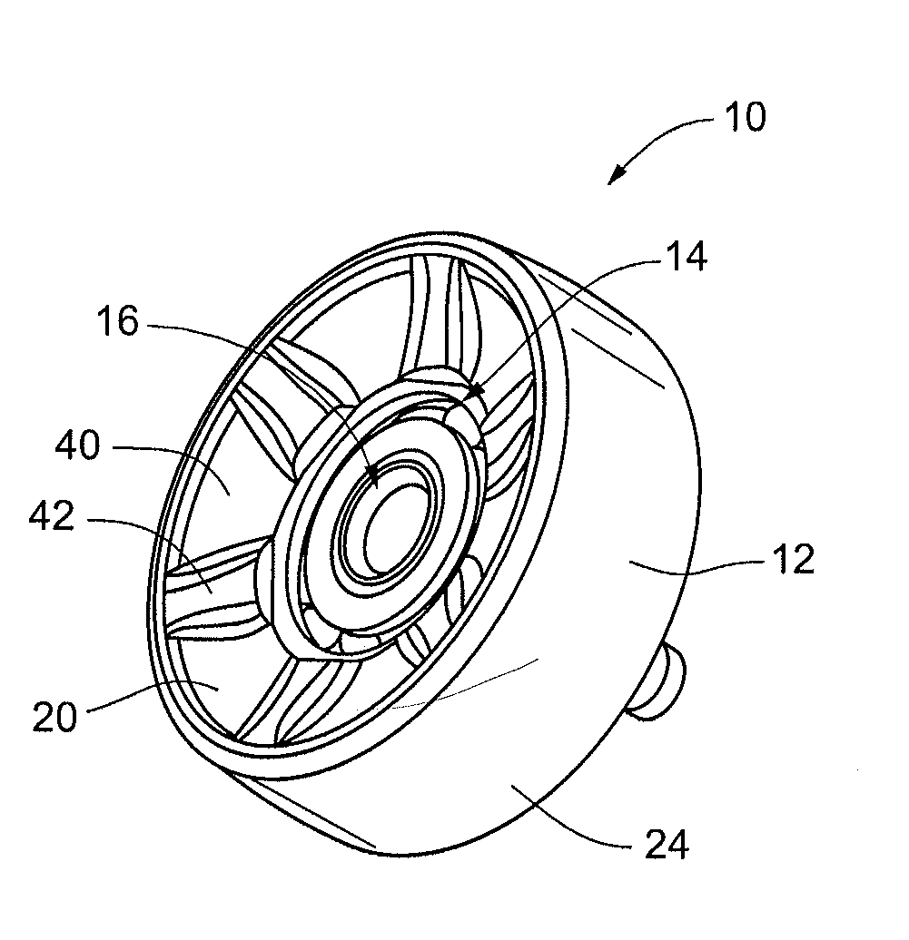
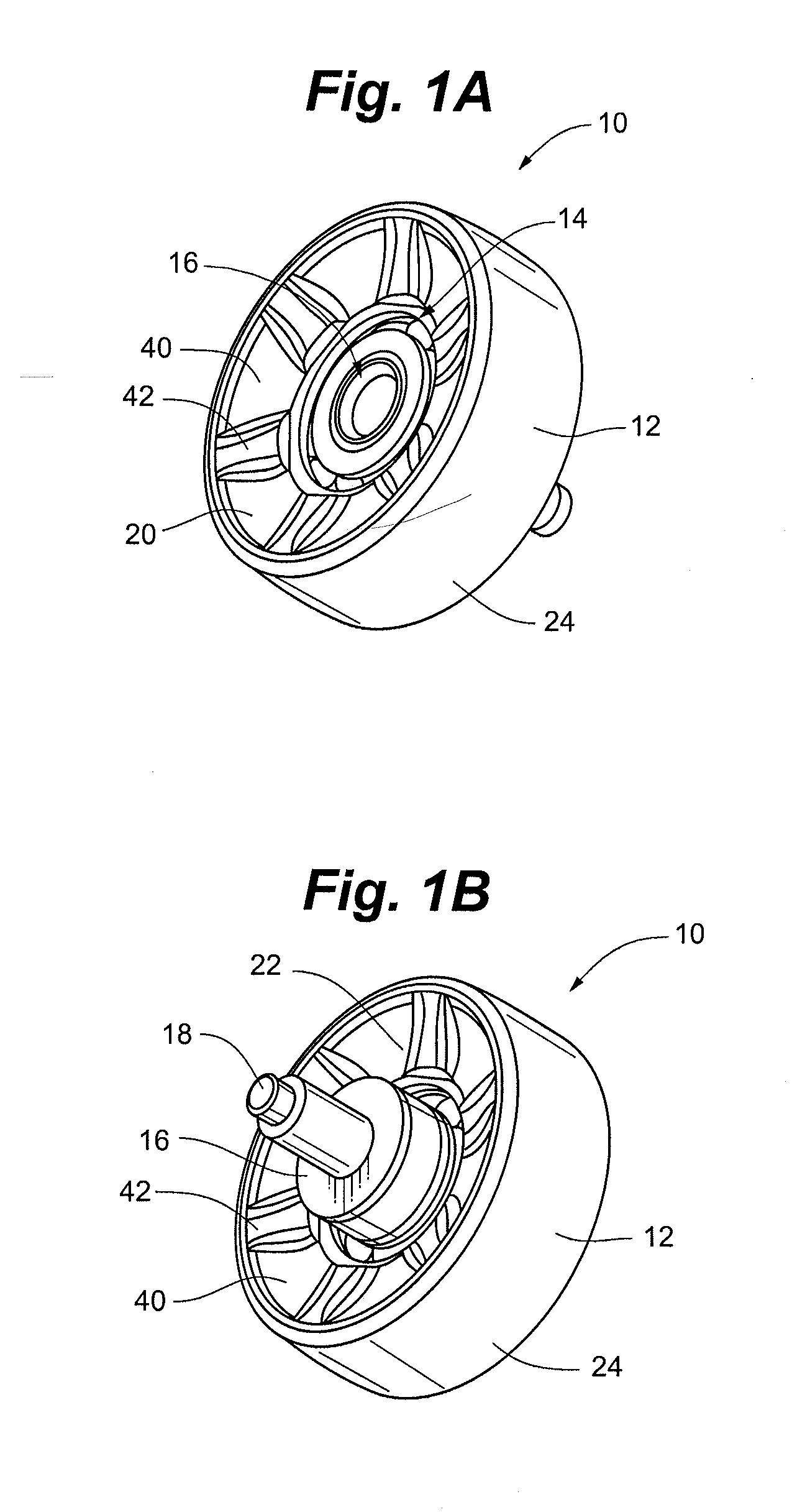
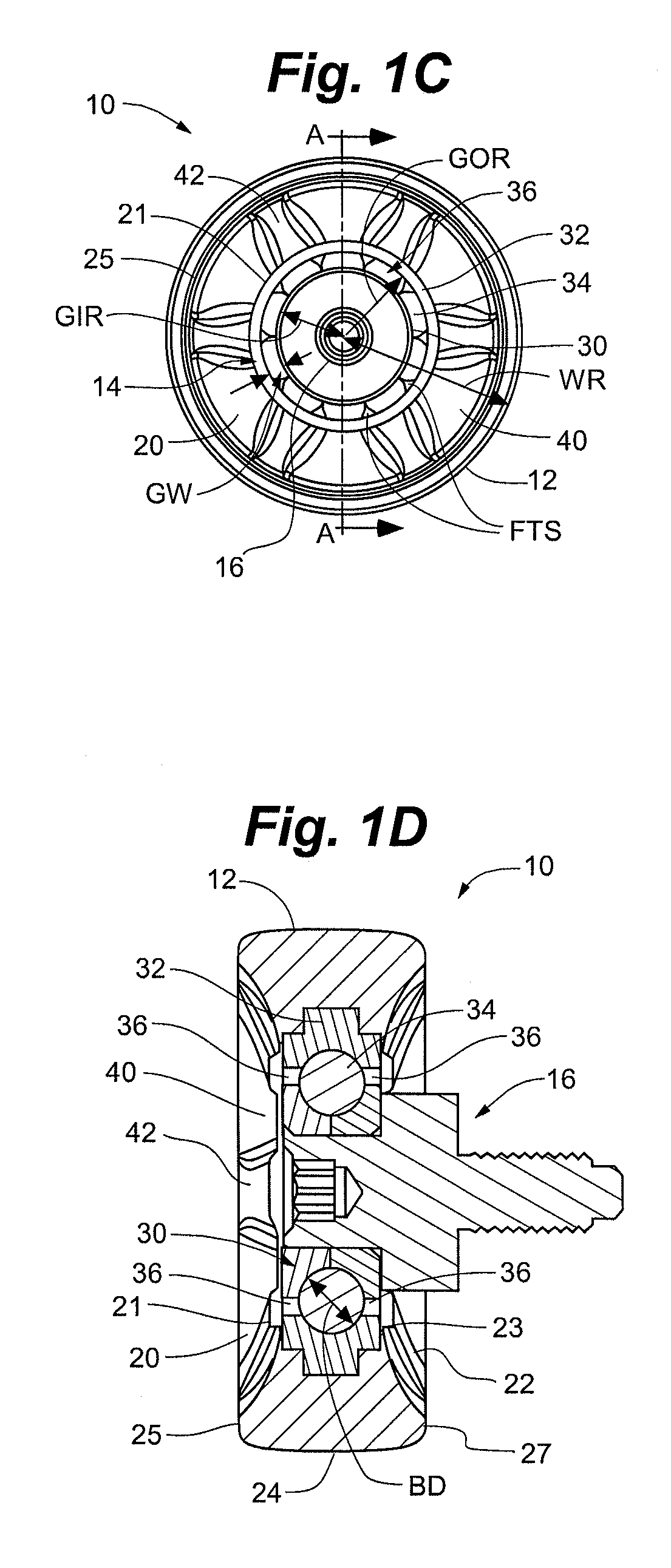
[0030]FIGS. 1A and 1B show front and back perspective views, respectively, of a trolley wheel assembly 10 according to an embodiment of the invention. The trolley wheel assembly 10 includes a wheel 12, a bearing assembly 14, and a hub 16. The illustrated hub 16 has a shaft 18 for coupling the trolley wheel assembly 10 to a trolley bracket, which forms part of a t...


PUM


Abstract

The invention provides a trolley wheel assembly for a conveyor system, e.g., an overhead conveyor system. In certain embodiments, the wheel assembly includes at least one wheel face having a contour (optionally a funneling configuration and / or one or more surface features) configured to facilitate flow of a fluid toward an open bearing assembly of the wheel assembly. In some embodiments, the wheel assembly includes an inner race, outer race, and bearings having a particular hardness arrangement, optionally together with a polymer wheel having certain filler features. Methods for cleaning such a trolley wheel assembly are also provided.

Description

BACKGROUND[0001]Overhead trolley conveyor systems are used in a variety of settings in manufacturing and fabricating plants (automotive assembly lines, paint finishing lines, etc.), as well as in food processing plants. A typical conveyor system includes a track, a number of trolley assemblies riding on the track, and a drive mechanism that moves the trolleys along the track. A basic trolley assembly includes one or more trolley wheel assemblies that ride on the track and some form of bracket capable of suspending an item from the track. Different trolley wheel assemblies are used depending upon the particular setting and performance requirements, but in general a trolley wheel assembly includes a wheel with some form of bearing assembly.[0002]During use, the trolley assemblies are subjected to a variety of environments in which the wheel assemblies can get dirty over a period of time. Trolley performance can degrade as the bearing assemblies become dirty. In many cases, debris and ...

Claims


Application Information

Patent Timeline
IPC IPC(8): B66C11/00F16H55/36B08B3/00
CPCB65G9/002B65G45/00F16C2326/58F16C2240/40F16C13/006F16C2235/00F16C35/067F16C19/06
Inventor BREYER, SCOTT T.STOEHR, KYLE C.
Owner OCONOMOWOC MFG
Learn More