Household energy management system and method for one or more appliances

a technology for energy management and household appliances, applied in non-electric variable control, process and machine control, instruments, etc., can solve the problems of no active control, many utilities are currently experiencing a shortage of electric generating capacity,

Inactive Publication Date: 2011-06-23
GENERAL ELECTRIC CO
View PDF23 Cites 112 Cited by
  • Summary
  • Abstract
  • Description
  • Claims
  • Application Information

AI Technical Summary

Benefits of technology

[0005]According to one aspect, a household energy management system for one or more appliances comprises a controller for managing power consumption within a household. The controller is configured to receive and process a signal indicative of one or more energy parameters of an associated energy utility. The controller includes a user interface for receiving energy management input for at least one appliance of the one of more appliances from a user. The controller at least one of controls and operates the at least one appliance in one of a plurality of operating modes, including at least a normal operating mode and an energy savings mode, in response to the input received by the user via the user interface in conjunction with the received signal.
[0006]According to another aspect, a household energy management system for one or more appliances comprises a controller for managing power consumption o

Problems solved by technology

Many utilities are currently experiencing a shortage of electric generating capacity due to increasing consumer demand for electricity.
Currently utilities generally charge a flat rate, but with increasing cost of fuel prices and high energy usage at certain parts of the day, utilities have to buy more energy to supply customers during peak demand.
This is undesirable because the consumer may not always be present in the

Method used


Image

  • Household energy management system and method for one or more appliances
  • Household energy management system and method for one or more appliances
  • Household energy management system and method for one or more appliances

Examples


Embodiment Construction

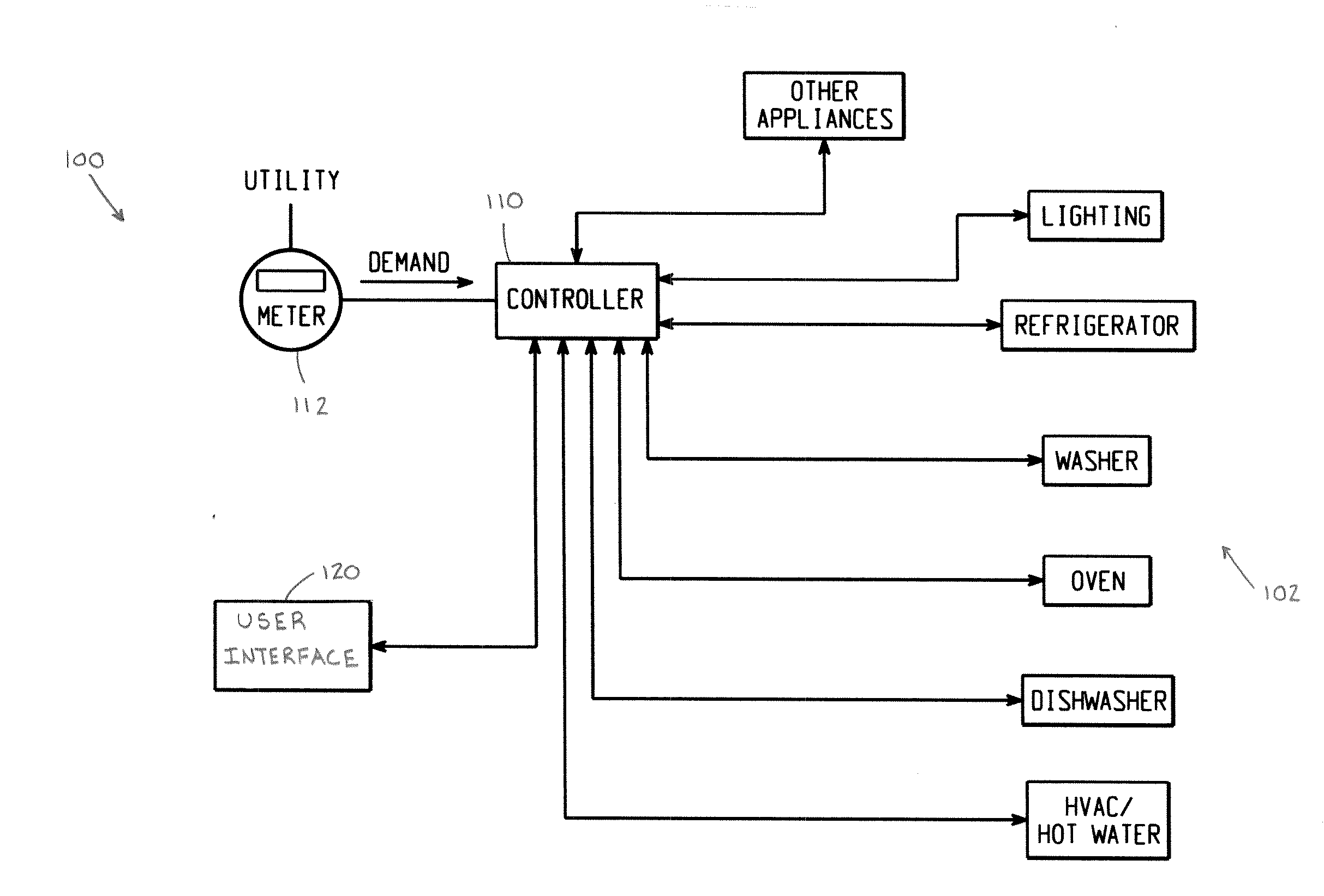
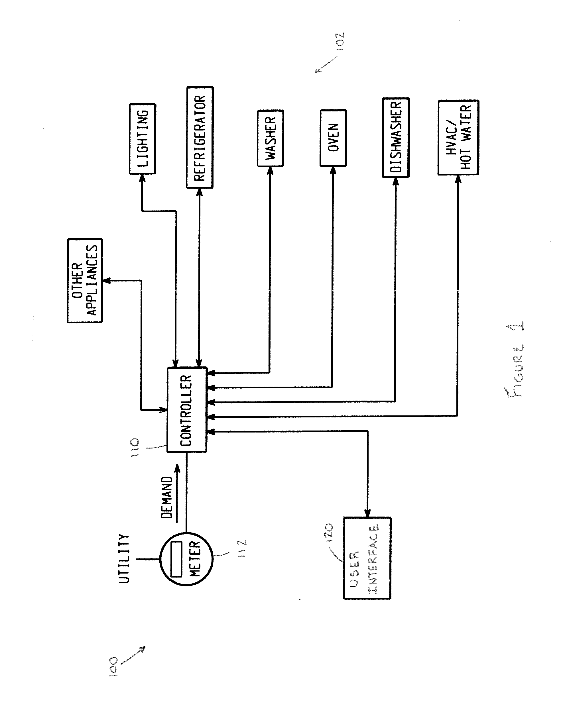
[0010]It should, of course, be understood that the description and drawings herein are merely illustrative and that various modifications and changes can be made in the structures disclosed without departing from the present disclosure. Referring now to the drawings, wherein like numerals refer to like parts throughout the several views, FIG. 1 schematically illustrates a household energy management system 100 for one or more appliances 102. The term “appliance” is used herein to include typical household appliances, for example a refrigerator, dishwasher, washer, dryer, microwave and oven, as well as an HVAC system, water heater and lighting. The energy management system comprises a controller 110, also referred to as a “home energy manager” (HEM), for managing power consumption of the one or more appliances within a household. The controller 110 can include a micro computer on a printed circuit board which is programmed to selectively control the energization of at least one power...


PUM


Abstract

A household energy management system and method for one or more appliances includes a controller for managing power consumption within a household. The controller is configured to receive and process a signal indicative of one or more energy parameters of an associated energy utility. The controller includes a user interface for receiving energy management input for at least one appliance of the one of more appliances from a user. The controller at least one of controls and operates the at least one appliance in one of a plurality of operating modes, including at least a normal operating mode and an energy savings mode, in response to the input received by the user via the user interface in conjunction with the received signal.

Description

BACKGROUND[0001]The present disclosure relates to energy management, and more particularly to power consuming device control methods and electrical energy consumption systems.[0002]Many utilities are currently experiencing a shortage of electric generating capacity due to increasing consumer demand for electricity. Currently utilities generally charge a flat rate, but with increasing cost of fuel prices and high energy usage at certain parts of the day, utilities have to buy more energy to supply customers during peak demand. Consequently, utilities are charging higher rates during peak demand. If peak demand can be lowered, then a potential huge cost savings can be achieved and the peak load that the utility has to accommodate is lessened. In order to reduce high peak power demand, many utilities have instituted time of use metering and rates which include higher rates for energy usage during on-peak times and lower rates for energy usage during off-peak times. As a result, consume...

Claims


Application Information

Patent Timeline
IPC IPC(8): G06F1/32
CPCF24F2011/0075G06Q10/04G06Q50/06H02J3/14H02J2003/143F24F2011/0047Y02B70/3266Y02B70/3275Y04S20/222Y04S20/242Y04S20/244Y02B70/3225F24F2140/60F24F11/46H02J2310/14Y02B70/30
Inventor THOMAS, GREGORY M.BESORE, JOHN K.CAPELLE, DANIEL RYANSANTANA, OMARBOWLEY, BRICE ALAN
Owner GENERAL ELECTRIC CO
Why Eureka
Try Eureka