
Fastening system for a plate-shaped structural element

a technology of structural elements and fastening systems, which is applied in the direction of photovoltaics, solar heat collectors for particular environments, heat collector mountings/supports, etc., can solve the problems of reducing the efficiency of the entire chain, requiring special production procedures, and increasing production costs

Active Publication Date: 2011-06-30
MONIER TECHN CENT
View PDF3 Cites 58 Cited by
  • Summary
  • Abstract
  • Description
  • Claims
  • Application Information

AI Technical Summary

Benefits of technology

[0008]It is an object of the present invention to provide a fastening system which makes it possible to also use plate-shaped structural elements, in particular large-surface-area photovoltaic laminates produced in series for on-roof installation, in modules for in-roof laying.

Problems solved by technology

A disadvantage in this connection is that an element which is in shade reduces the efficiency of the entire chain.
This makes production more expensive and requires special production procedures.

Method used


Image

  • Fastening system for a plate-shaped structural element
  • Fastening system for a plate-shaped structural element
  • Fastening system for a plate-shaped structural element

Examples


Embodiment Construction

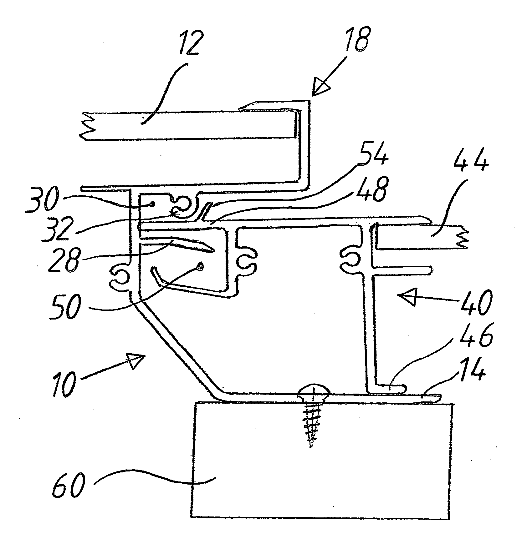
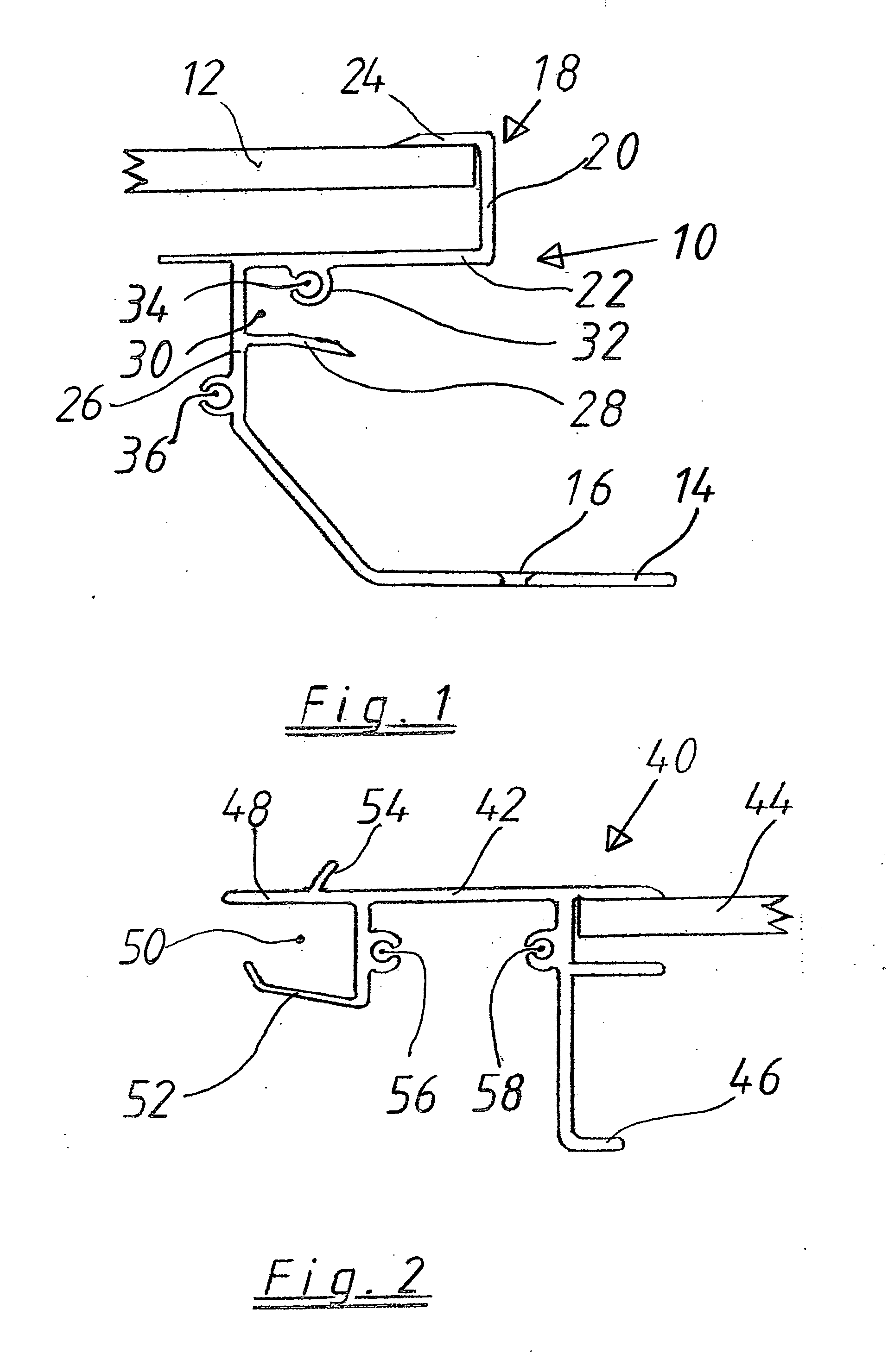
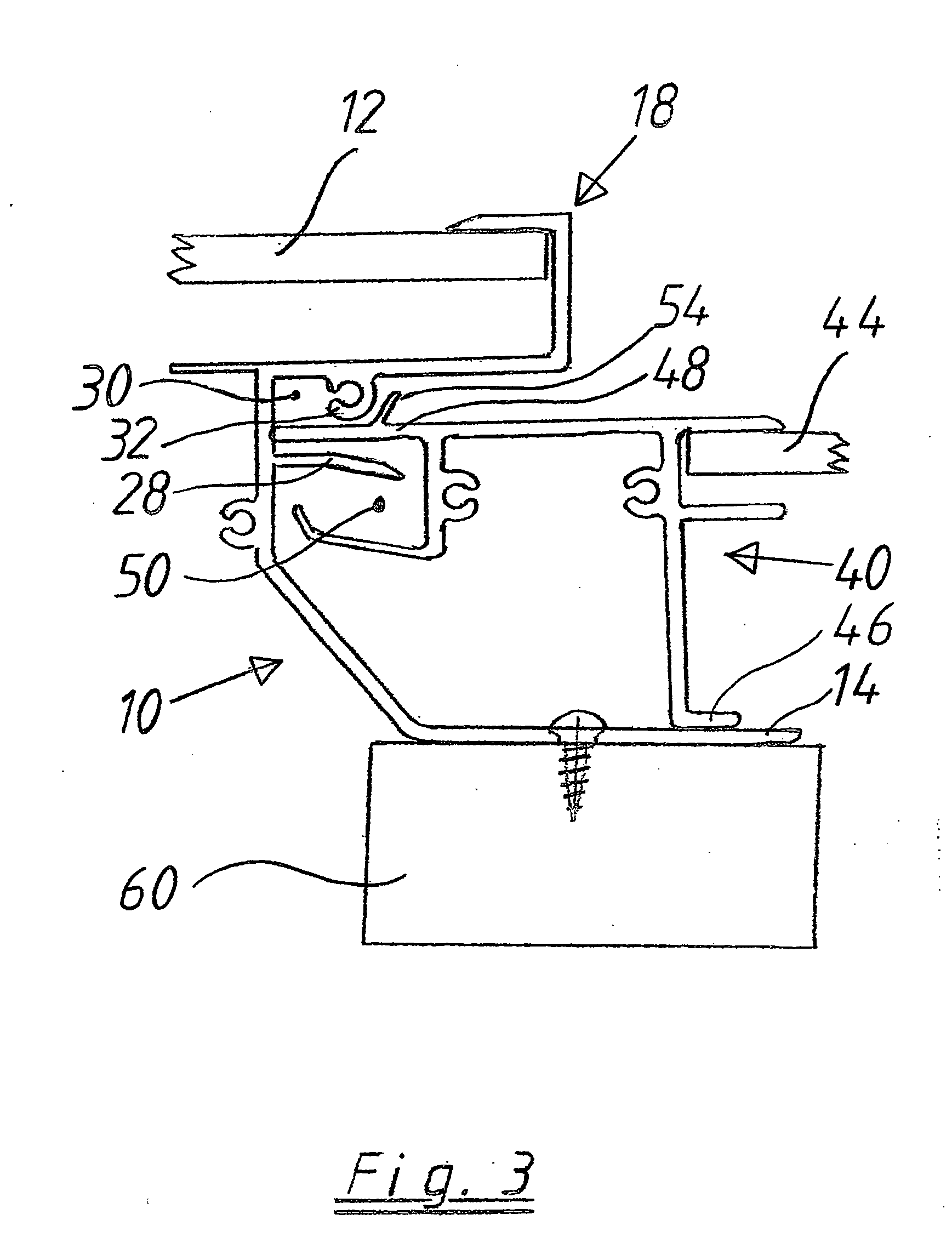
[0027]FIG. 1 schematically shows a cross section of an eaves-side cross beam 10 with an edge portion of a first plate-shaped structural element 12, here a laminate measuring 80×160 cm having photovoltaic elements. The bottom side of the eaves-side cross beam 10, an extruded profile of an aluminum alloy, has a support 14 which protrudes in the direction of the eaves and has screw holes 16 for fastening to the roof structure. The top side of the eaves-side cross beam 10 is provided with a U-shaped mounting 18 which surrounds the edge of the plate-shaped structural element 12. The U-shaped mounting 18 has a base 20 of the U, a lower limb 22 of the U and an upper limb 24. The upper limb 24 is joined to the plate-shaped structural element 12 by an adhesive. A web 26 that leads to the support 14 extends from the lower limb 22 of the mounting 18 and, on its side which points toward the eaves, has a downwardly curved protrusion 28 beneath the mounting 18, as a result of which a channel 30 i...


PUM


Abstract

A fastening system for a plate-shaped structural element on a pitched roof is provided. The plate-shaped structural element is bordered in a water-tight manner in a frame and fully replaces the roof covering, and the eaves-side and ridge-side cross beams of the frame which run transversely to the ridge-eaves direction have profiles which are matched to each other and engage in each other. The top side of the eaves-side cross beam has a mounting that surrounds the edge of the plate-shaped structural element, and the bottom side thereof has a support for fastening to the roof structure. The support includes a web that extends from the mounting to the support, a protrusion extending beneath the mounting receives an extension that extends from the ridge-side cross beam thereof.

Description

CROSS REFERENCE TO RELATED APPLICATIONS[0001]This application is a National Stage entry of International Application No. PCT / DE2009 / 000140, which was filed on Jan. 30, 2009, which claims the benefit of German Patent Application No. 10 2008 007 334.2, filed Feb. 2, 2008, the entire contents of both of which are incorporated herein by reference.BACKGROUND OF THE INVENTION[0002]1. Field of the Invention[0003]The invention relates to a fastening system for a plate-shaped structural element on a pitched roof, wherein the plate-shaped structural element is bordered in a water-tight manner in a frame of profiled beams, to form a module, and fully replaces the roof covering, wherein the eaves-side and ridge-side cross beams of the frame which run transversely to the ridge-eaves direction have profiles which are matched to each other and engage in each other in order to install modules which are adjacent in the ridge-eaves direction, these profiles forming a rain-proof joint such that the mo...

Claims


Application Information

Patent Timeline
Patent Type & Authority Applications(United States)
IPC IPC(8): E04D13/18E04B1/38
CPCF24J2/045F24J2/4614F24J2/5211F24J2002/0061H02S20/23Y02B10/20Y02E10/44Y02E10/47Y02B10/12F24S20/67F24S25/20F24S2020/13F24S40/44Y02E10/50Y02B10/10
Inventor WELTER, CHRISTIANNEUNER, ROLANDSCHWEIZER, ROLAND
Owner MONIER TECHN CENT
Learn More