Hydraulic brake system

a hydraulic brake and hydraulic technology, applied in the direction of cycle brakes, steering devices, cycle equipment, etc., can solve the problems of inconvenient assembly of conventional mechanical systems, inability to meet the needs of users,

Inactive Publication Date: 2011-07-07
ASHIMA LTD
View PDF13 Cites 24 Cited by
  • Summary
  • Abstract
  • Description
  • Claims
  • Application Information

AI Technical Summary

Benefits of technology

The main objective of the present invention is to provide an improved hydraulic brake system which is extensive utilized in all kinds of bike.

Problems solved by technology

However, the conventional mechanical system requires a lot of element such that it is inconvenient to assemble the conventional mechanical system.
The various elements also cause the conventional mechanical system to be unstable.
All elements are operated together such that it takes strenuous strength for a user.
However, each hydraulic device has hydraulic fluid filling therein such that the two hydraulic devices are heavy.
Those are not suitable for the requirement of the light weight bike.
This costs a lot to re-thread the handlebar and increases a manufacturing fee of each bike.
Besides, the conventional hydraulic brake system is not able to mount on a mountain bike.
Therefore, a receiving space of the handlebar is more decreased and is not able to assemble with the conventional hydraulic brake system.

Method used


Image

  • Hydraulic brake system
  • Hydraulic brake system
  • Hydraulic brake system

Examples


Embodiment Construction

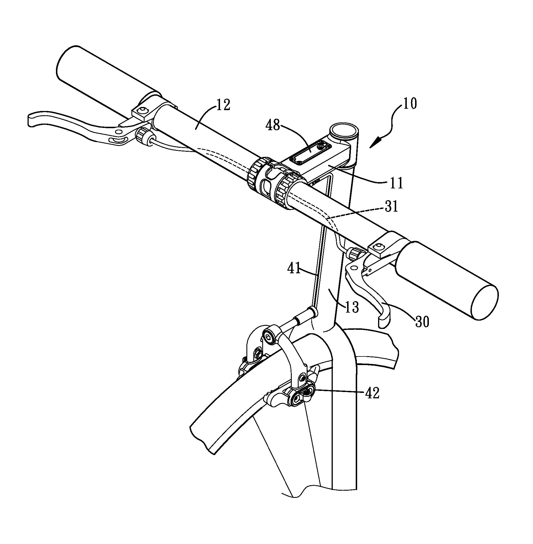
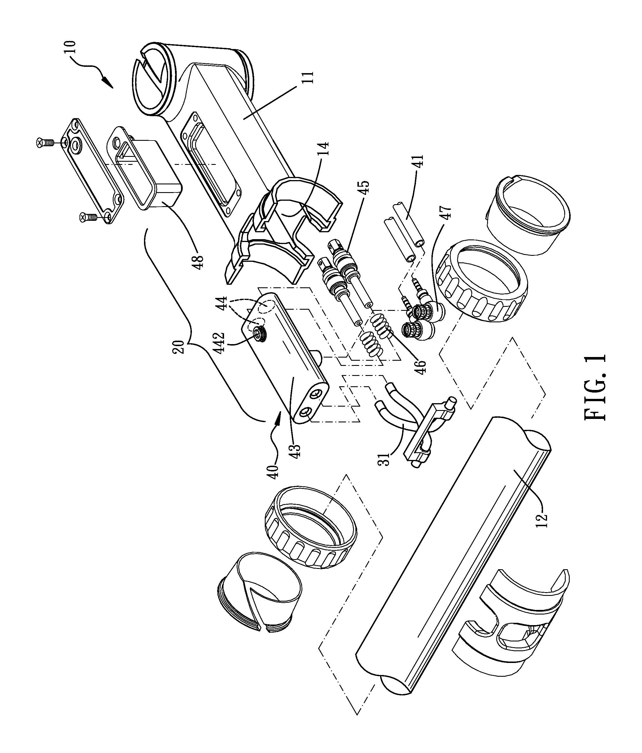
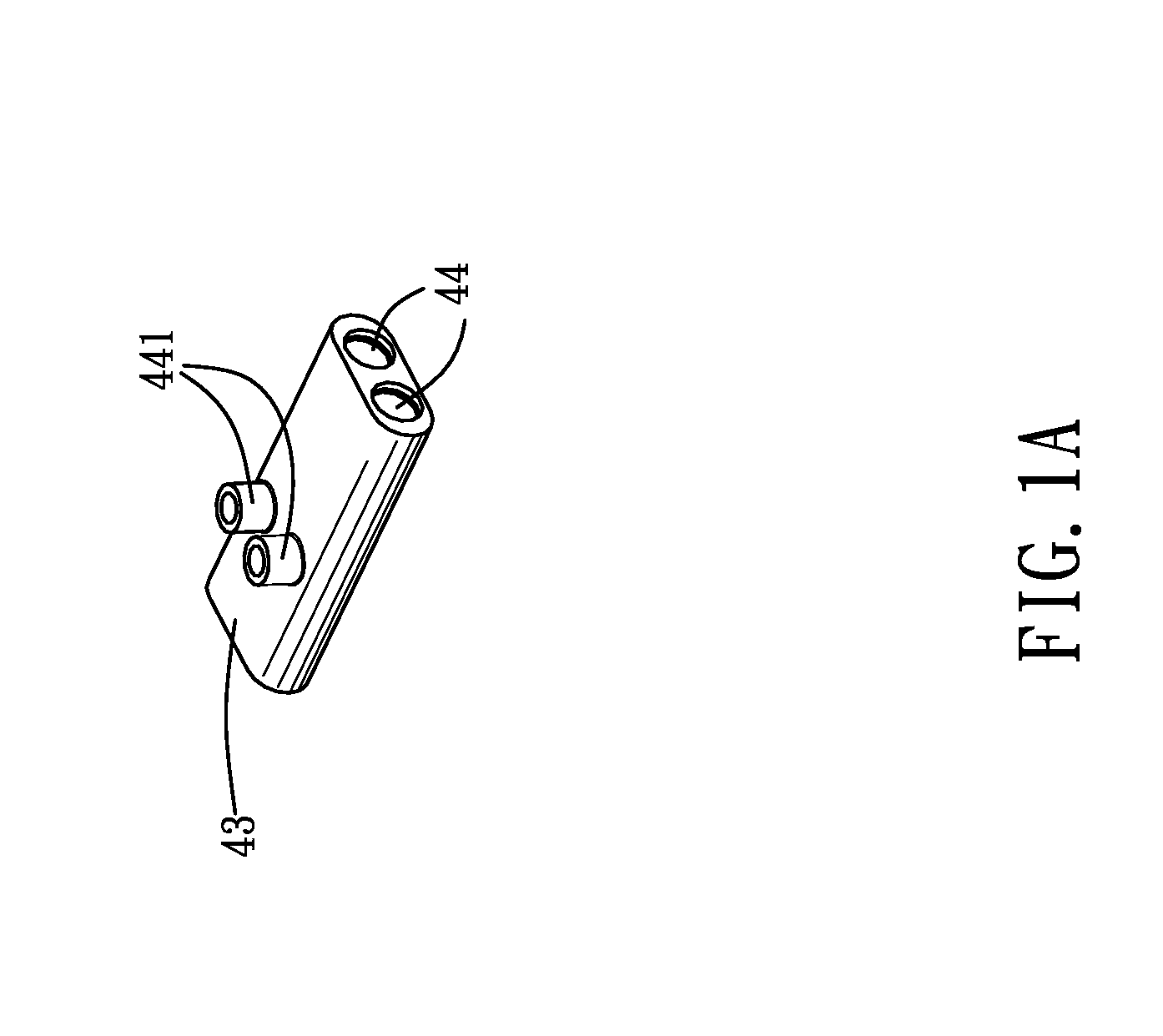
Referring to the drawings and initially to FIGS. 1-6, a hydraulic brake system in accordance with the present invention comprises a bicycle steering assembly 10. The bicycle steering assembly 10 includes a head tube 13, a connecting member 11 connected with the head tube 13 and a handlebar 12 mounted on the connecting member 11. In the preferred embodiment of the present invention, the connecting member 11 can be a stem, or a head tube. The connecting member 11 has a receiving portion 14 disposed therein. A hydraulic device 20 is mounted in the receiving portion 14. The hydraulic device 20 includes a hydraulic braking mechanism 40 and at least one connecting tube 41 connected with the hydraulic braking mechanism 40. The hydraulic braking mechanism 40 has a hydraulic container 43 mounted in the connecting member 11. The hydraulic container 43 has two hydraulic tanks 44 disposed therein for receiving fluid. The hydraulic container 43 has two first connecting holes 441 defined in a bot...


PUM


Abstract

A hydraulic brake system includes a bicycle steering assembly having a head tube, a connecting member connected with the head tube and a handlebar mounted on the connecting member. The connecting member has a receiving portion disposed therein. A hydraulic device is mounted in the receiving portion. The hydraulic device includes a hydraulic braking mechanism and at least one connecting tube connected with the hydraulic braking mechanism. A braking device is adapted to mount on a wheel of the bicycle. The at least one connecting tube is connected with the braking device. Two brake levers are respectively mounted on two ends of the handlebar. Each brake lever has a brake cable connected therewith. The brake cable has one end connected to a corresponding brake lever and the other end connected to the hydraulic brake mechanism for relatively driving the brake device.

Description

BACKGROUND OF THE INVENTION1. Field of the InventionThe present invention relates to a brake system, and more particularly to a holder for a hydraulic brake system used for reducing volume and weight.2. Description of Related ArtA conventional brake system has a mechanical structure and is relied on leverage to pull a cable. However, the conventional mechanical system requires a lot of element such that it is inconvenient to assemble the conventional mechanical system. The various elements also cause the conventional mechanical system to be unstable. Furthermore, the conventional mechanical system is simultaneously operated. All elements are operated together such that it takes strenuous strength for a user. Each element is related to other elements such the tolerance and gaps between the elements will consume the braking effect.A conventional hydraulic brake system includes two brake devices respectively mounted on two handlebars of a bike and two hydraulic devices respectively mou...

Claims


Application Information

Patent Timeline
Patent Type & Authority Applications(United States)
IPC IPC(8): B62L3/02B60T7/08B60T11/10
CPCB60T17/04B60T11/16B62J2099/0046B62K21/12B62J11/13B62L3/023
Inventor MOORE, WAYNE-IAN
Owner ASHIMA LTD
Why Eureka
Try Eureka