
Shelf with LED assembly

a technology of led assembly and shelf, which is applied in the field of shelves with led assembly, can solve the problem of relatively heavy volume of stamped metal

Active Publication Date: 2011-07-07
SSW ADVANCED TECH LLC
View PDF38 Cites 52 Cited by
  • Summary
  • Abstract
  • Description
  • Claims
  • Application Information

AI Technical Summary

Benefits of technology

[0017]In accordance with the invention, a shelf assembly is adapted for use in a refrigerator and other articles. The shelf assembly includes a shelf and support means for supporting the shelf at a desired height. Securitng means are provided for securing the shelf to the support means. A first plurality of LEDs is positioned in proximity t...

Problems solved by technology

In addition, the volume of stamped metal can be relatively heavy.
Still further, sideplates formed of solid pieces of stamped metal often prohibit any substantial amount of light transmission or air flow around the sideplates that support shelving articles.
However, various types of light sources using LED's with refrigerator shelves have shown various disadvantages.

Method used


Image

  • Shelf with LED assembly
  • Shelf with LED assembly
  • Shelf with LED assembly

Examples


first embodiment

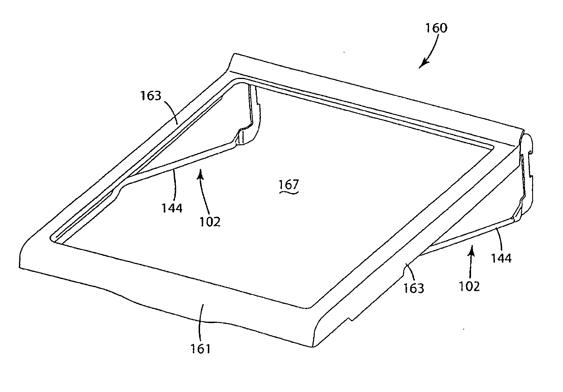
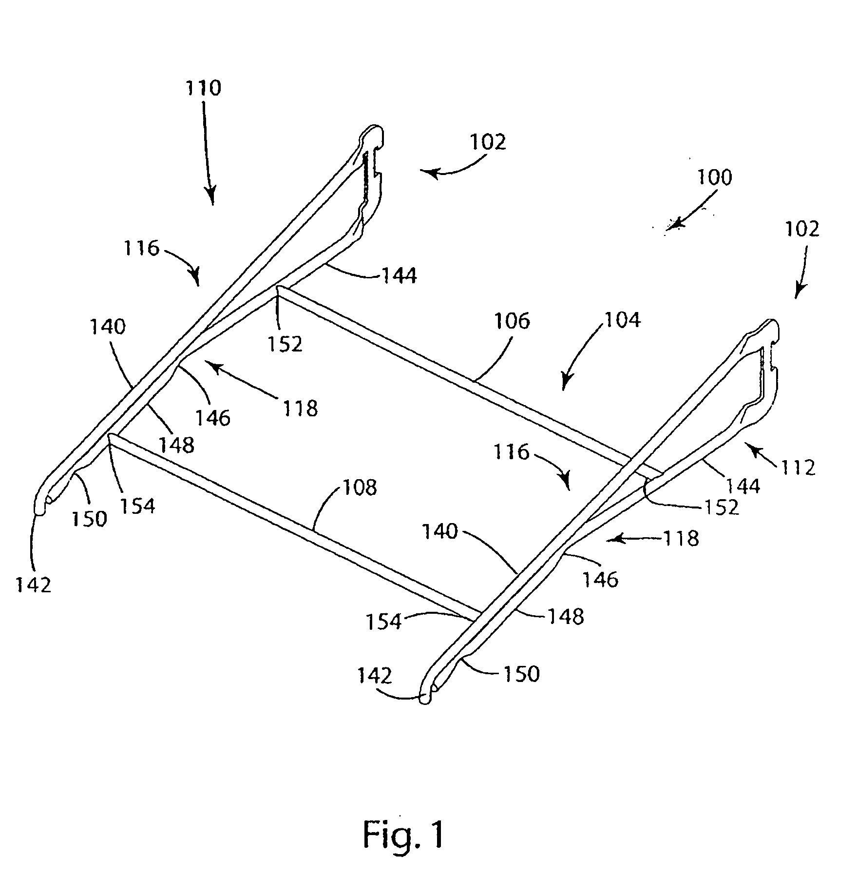
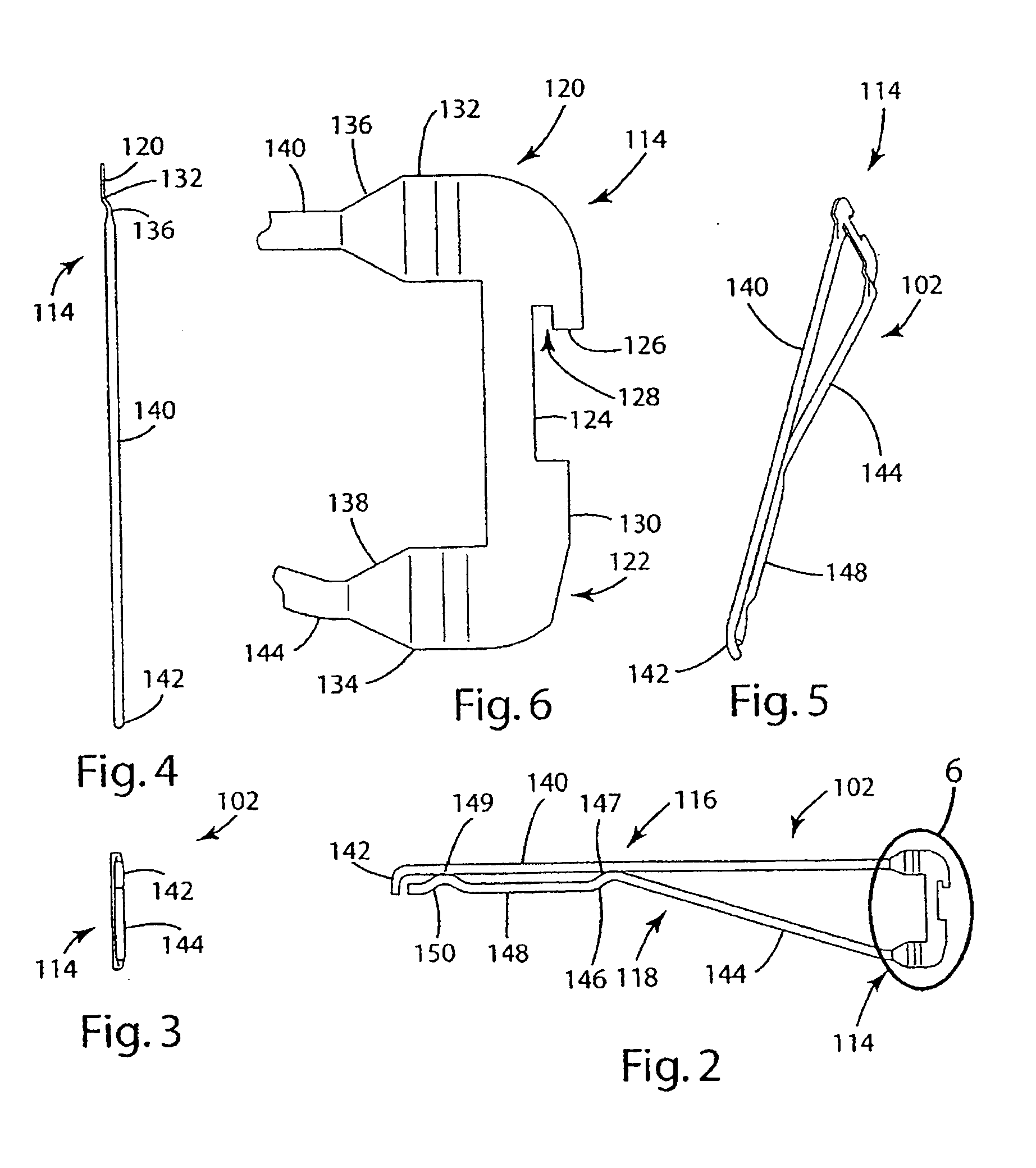
[0099]Turning to the drawings, an assembly or frame utilizing wire sideplates is identified as wire sideplate frame 100, as illustrated in FIG. 1. The wire sideplate frame 100 illustrated in FIG. 1 employs a pair of opposing wire sideplates 102. For purposes of description, one of the wire sideplates 102 is identified in FIG. 1 as left hand wire sideplate 110, while the other is identified as right hand wire sideplate 112. The references to “left hand” and “right hand” are for purposes of identification only, and have no specific meaning with respect to concepts of the invention. As further illustrated in FIG. 1, the wire sideplates 102 are shown in opposing lateral positions, and are interconnected by a rear transverse support rod 106 and a front transverse support rod 108. For purposes of support and rigidity, the rear transverse support rod 106 may be interconnected to each of the wire sideplates 102 through weld points 152. Correspondingly, the front transverse support rod 108 m...

second embodiment

[0163]a shelving assembly in accordance with the invention is illustrated in FIGS. 49, 50 and 51, and is referred to herein as shelving assembly 540. For purposes of clarity and descriptiveness, elements in any given version of a shelving assembly in accordance with the invention as described herein which are substantially similar to or otherwise identical to elements previously described herein will be given identical reference numbers, and will not be described in detail. With reference to FIGS. 49-51, the shelving assembly 540, like the shelving assembly 500 previously described herein, can be used with a refrigerator liner 502 and cantilever ladders 504. Also, the shelving assembly 540 utilizes sheet metal sidearms 506 having ladder connectors 508. The ladder connectors 508 connect into ladder notches 510. A refrigerator shelf 516 is mounted to the sidearms 506 in a manner which can be identical to that previously described with respect to shelving assembly 500. The shelving ass...


PUM


Abstract

A shelving assembly (500) includes a pair of sheet metal sidearms (506) having ladder connectors (508) releasably coupled to cantilever ladders (504). An LED strip (520) having spaced apart LEDs is positioned immediately behind a refrigerator shelf (516). A rear form (522) is used for securing the LED strip (520) to a refrigerator shelf (516). The LED strip (520) is powered through electrical contact modules (524) which conductively connect to low voltage power strips (534).

Description

CROSS-REFERENCE TO RELATED APPLICATIONS[0001]This application claim priority of U.S. Provisional Patent Application Ser. No. 61 / 058,902 filed Jun. 4, 2008, and U.S. Provisional Patent Application Ser. No. 61 / 090,002, filed Aug. 19, 2008.STATEMENT REGARDING FEDERALLY SPONSORED RESEARCH OR DEVELOPMENT[0002]Not applicable.REFERENCE TO A MICROFICHE APPENDIX[0003]Not applicable.BACKGROUND OF THE INVENTION[0004]1. Field of the Invention[0005]The invention relates to shelving articles adapted for use in various environments and, more particularly, to shelving articles adapted for use in environments such as refrigerators, with the shelving articles assisting in providing a light source.[0006]2. Background Art[0007]Various types of prior art shelving have been developed for use in a number of environments. Along with this shelving, use is often made of support bracing. This support bracing and these shelving articles are often adapted for use in environments such as refrigerators, store fix...

Claims


Application Information

Patent Timeline
IPC IPC(8): F21V33/00F25D25/02F25D27/00
CPCA47B57/42A47B96/02A47B96/027A47B96/028F25D27/00F21W2131/305F21Y2101/02F25D25/02A47B2220/0077F21Y2115/10F25D2400/40
Inventor DRIVER, JOHN PATRICKMCMILLIN, MATTHEWNALL, BRADLEY M.YOCHUM, JASON ROBERT
Owner SSW ADVANCED TECH LLC
Learn More