Fiber optic rotary joint using tec fiber

a technology fiber optic fibers, applied in the field of single channel can solve the problems of increasing the size and cost using high-quality lenses, and difficult fabrication of fiber optic rotary joints, so as to reduce the loss of insertion, and increase the return loss

Inactive Publication Date: 2011-07-07
PRINCETEL
View PDF18 Cites 32 Cited by
  • Summary
  • Abstract
  • Description
  • Claims
  • Application Information

AI Technical Summary

Benefits of technology

[0006]The first object of the present invention is to minimize the need for maintaining precise axial alignment between the rotating and non-rotating elements of a single channel fiber optic rotary joint so that it could be used in any harsh environments such as temperature change, vibration and shock.
[0007]Another object of the present invention is to provide a single channel fiber optic rotary joint with a very low-profile and compact design.
[0008]A further objective of the preset invention is to reduce the insertion loss and increase return loss and to allow the rotary joint to work at any ambient pressure by filling index-matching fluid.

Problems solved by technology

Comparing with its electrical counterpart, the electrical slip ring, the Fiber optic Rotary Joint is not easy to fabricate because the transmission of the light beam through a fiber is strongly depend on its geometrical structure and related position.
First, this kind of rotary joint require special fixture to have lenses aligned.
Secondly, using high quality lenses would increase the sizes and cost of fiber optic rotary joints.
Further, to maintain the axial alignment is difficult so that this kind of rotary joint is vulnerable in such environments as temperature change, vibration, and shock.

Method used


Image

  • Fiber optic rotary joint using tec fiber
  • Fiber optic rotary joint using tec fiber
  • Fiber optic rotary joint using tec fiber

Examples


Embodiment Construction

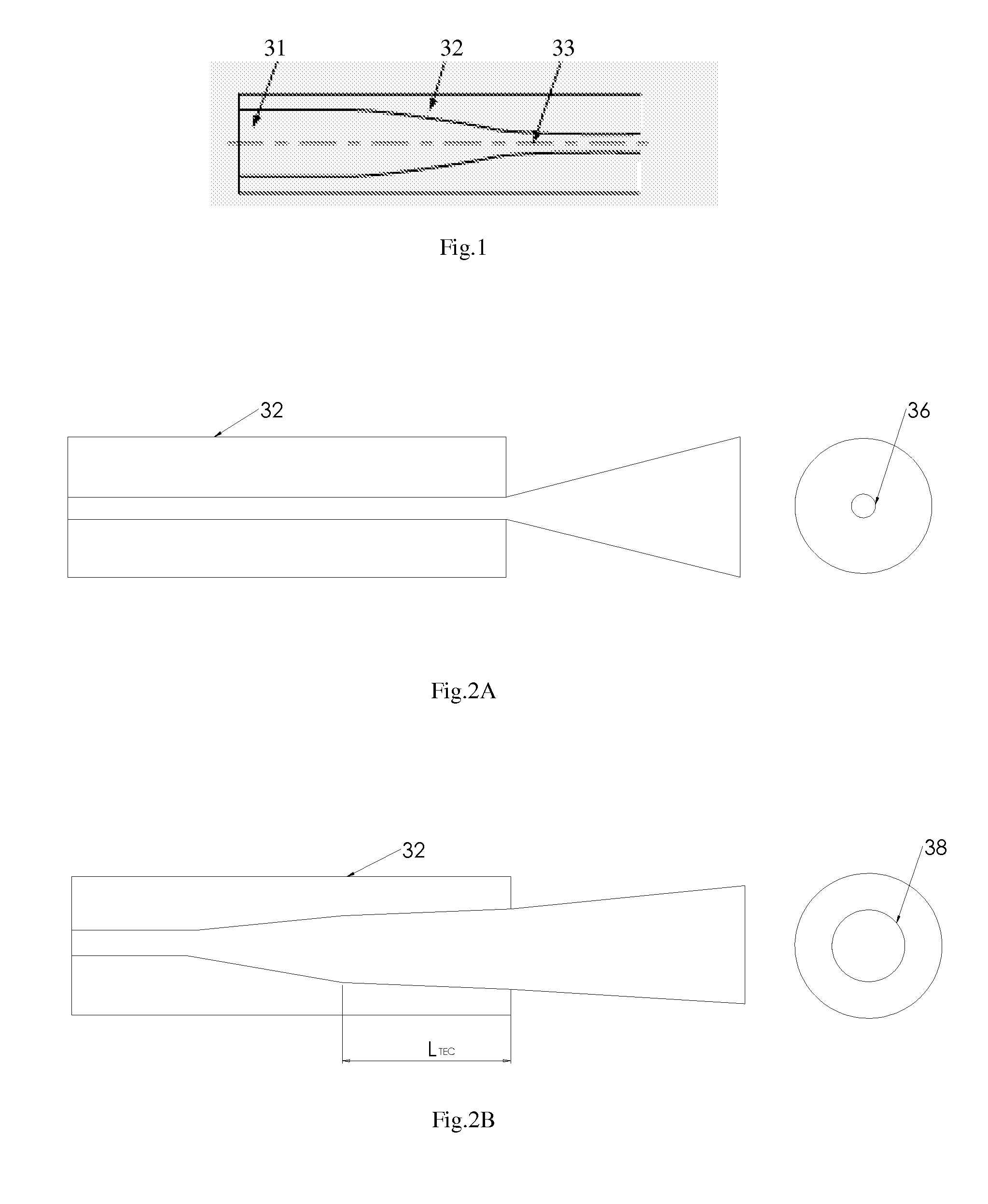
[0012]A TEC fiber is fabricated such that a flame is applied in close proximity to an optic fiber, using a torch which generates a high temperature heat and then the optic fiber is thermally treated at a high temperature lower than the fusion point to expand the core of the optic fiber. So the TEC fiber is called Thermally expand core fiber. It is a significant fiber device to reduce the coupling loss induced by optical alignment error between two different core Single Mode (SM) fibers and between the SM fiber and the laser diode, and during assembling of optical TEC fibers. It is much easier for the alignment of TEC fibers comparing with conventional optic fibers without use of collimators.

[0013]As illustrated in FIG. 1, the core 33 of an optic fiber 32 is thermally expanded as 31.

[0014]FIG. 2A and FIG. 2B shows the difference between fibers without TEC treatment and with TEC treatment. Fiber 32 has a normal core 36 in FIG. 2A before TEC treatment and after TEC treatment the core i...


PUM


Abstract

A fiber optic rotary joint is invented using TEC (Thermally Expanded Core) fiber. This device has a rotatable optic TEC fiber and a stationary optic TEC fiber in an assembly to convey a light beam in the optic TEC fibers. The assembly also includes a stationary optic TEC fiber holder for fixing the tip of stationary optic TEC fiber in a central hole and a rotatable optic TEC fiber holder for fixing the body of the rotatable optic TEC fiber with the tip of the rotatable optic TEC fiber protruding out of the rotatable optic TEC fiber holder. The two optic TEC fiber holders can be rotated relative to each other so as to allow the tip of rotatable optic TEC fiber to rotate in the central hole on the stationary optic TEC fiber holder with the facets of the two optic TEC fiber adjacent very closely.

Description

BACKGROUND OF THE INVENTION[0001]1. Field of the Invention[0002]The invention is related to single channel fiber optic rotary joint in the field of optic communication to ensure that the device has low insertion loss, small insertion loss variation, and high return loss.[0003]2. Description of Related Art[0004]The Fiber optic Rotary Joint is the optic equivalent of the electrical slip ring. It allows uninterrupted transmission of an optic signal in a fiber guide through a rotational interface to a stationary apparatus. The Fiber optic Rotary Joint is widely used in missile guidance systems, robotic systems, remotely operated vehicles, oil drilling systems, sensing systems, and many other field applications where a twist-free fiber cable is essential. Combined with electrical slip rings or fluid rotary joints, Fiber optic Rotary Joint adds a new dimension to traditional slip rings. As fiber optic technology advances, more and more traditional slip ring users will benefit from Fiber o...

Claims


Application Information

Patent Timeline
Patent Type & Authority Applications(United States)
IPC IPC(8): G02B6/26G02B6/36
CPCG02B6/3604G02B6/2552
Inventor ZHANG, BOYING B.ZHANG, HONG
Owner PRINCETEL
Why Eureka
Try Eureka