Device for locking a bathroom door

a technology for locking devices and bathrooms, which is applied in the direction of building locks, construction, building construction, etc., can solve the problem that devices do not enable the partially-sighted to be informed

Inactive Publication Date: 2011-07-14
SOC NAT DES CHEMINS
View PDF20 Cites 3 Cited by
  • Summary
  • Abstract
  • Description
  • Claims
  • Application Information

AI Technical Summary

Benefits of technology

[0025]In practice, the information mechanism can be positioned on the door inside the cubicle. In this way, once the lock

Problems solved by technology

However, such locking devices do not enable the partially-sighte

Method used


Image

  • Device for locking a bathroom door
  • Device for locking a bathroom door
  • Device for locking a bathroom door

Examples


Embodiment Construction

[0030]As previously stated, the invention relates to a device for locking the door of a toilet cubicle.

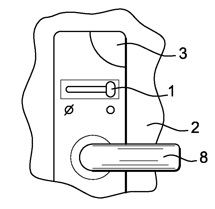
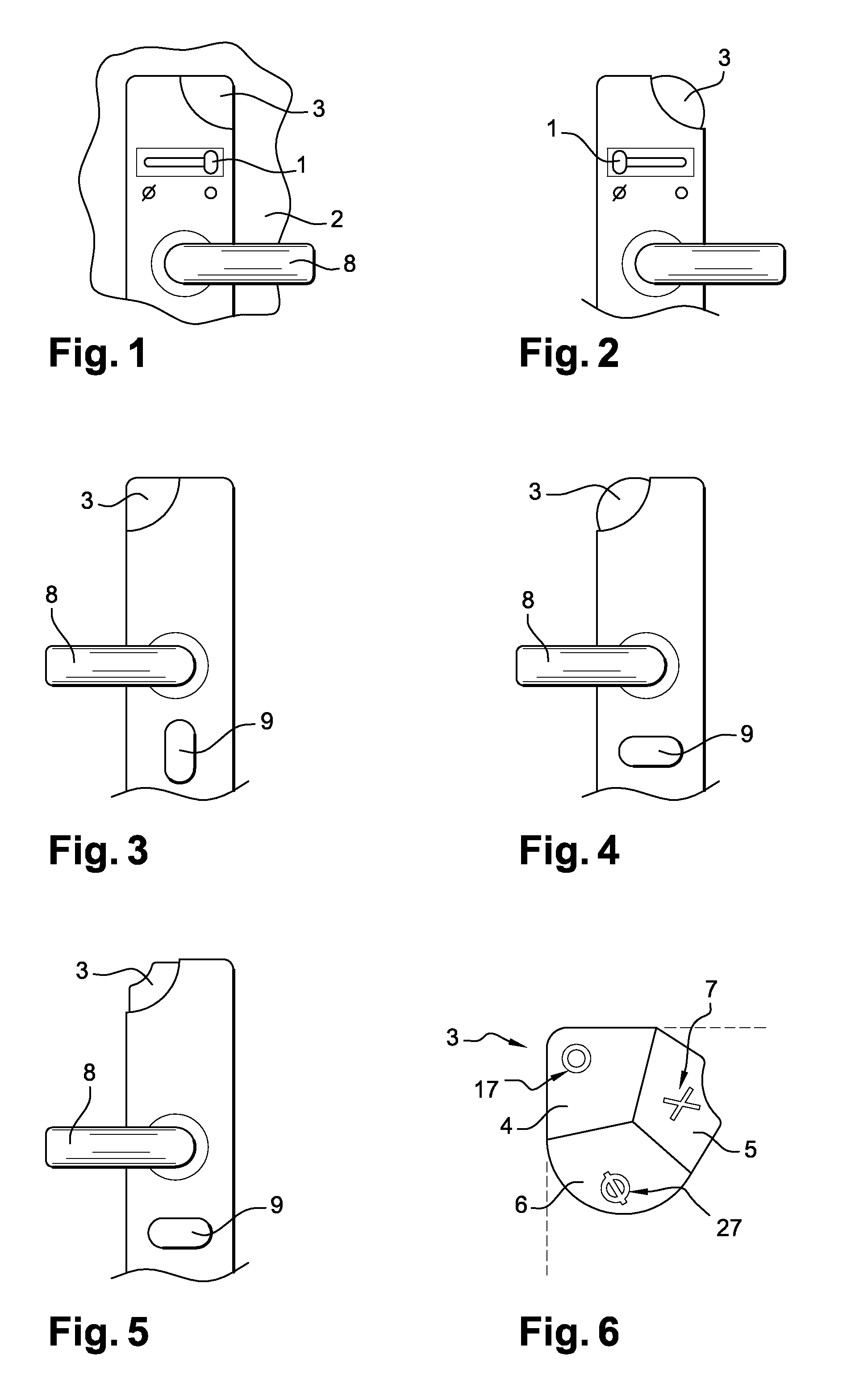
[0031]As shown in FIG. 1, such a locking device comprises a locking element (1) located inside the cubicle and enabling the door (2) to be locked or opened by means of a handle (8). Furthermore, the locking device includes an information mechanism (3) which can be positioned on the inside of the door to provide information for the occupant.

[0032]As shown in FIG. 2, when a person wishes to lock the cubicle door, he / she moves the locking element (1) to select the cubicle-engaged state and lock the door. At the same time, the information mechanism (3) changes shape in order to enable a partially-sighted user to check the selected state of the cubicle.

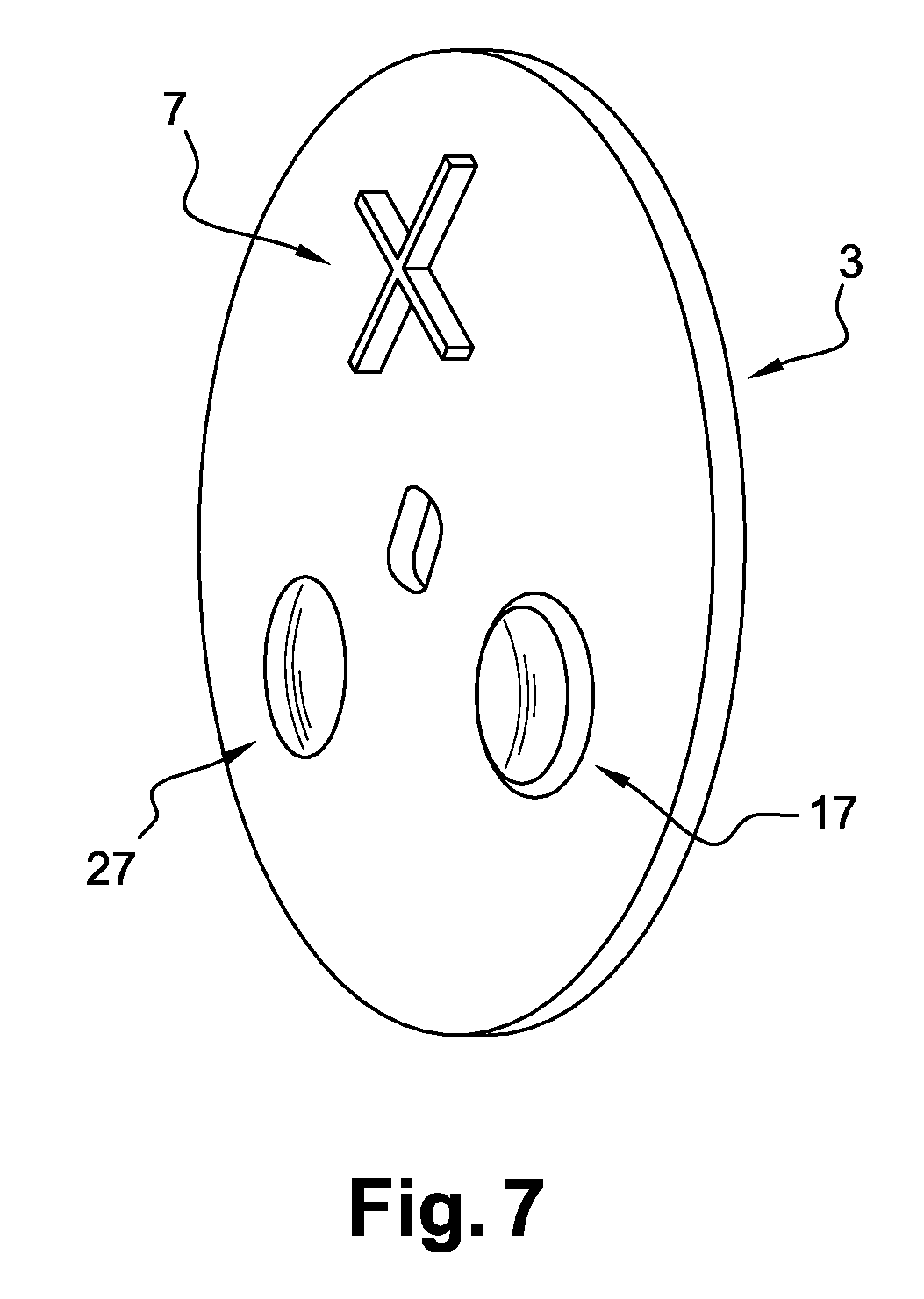
[0033]As shown in FIG. 3, the locking device also has an information mechanism (3) located on the outside of the cubicle. The state selected is the vacant state of the cubicle. Moreover, a lock (9) can enable an authorised person to lock ...


PUM


Abstract

Device for locking the door of a toilet cubicle comprising a door locking element operated manually from inside the cubicle, the said locking element allowing the vacant and engaged states of the cubicle to be selected and the door to be locked when the engaged state is selected, the said device including an information mechanism located on the door at least on the outside of the cubicle and providing at least two tactile and visual indicators of the state selected by the locking element, characterized in that the information mechanism includes raised pictograms to provide a tactile indicator.

Description

CROSS REFERENCE TO RELATED APPLICATIONS[0001]This application is a National Stage application under 35 U.S.C. §371 of PCT Application No. PCT / FR2009 / 051757, filed Sep. 18, 2009, which claims priority to French Application No. FR 0856264, filed Sep. 18, 2008, entitled “Device for Locking a Bathroom Door.”FIELD OF THE INVENTION[0002]The invention relates to the field of devices for locking a door from inside a room that is to be locked. This invention concerns more particularly devices for locking the door of a toilet cubicle that may be installed, on the one hand, in railway vehicles but also in aircraft, road vehicles or ships, and on the other hand, in public places such as stations, museums, restaurants, hotels or public highways.BACKGROUND OF THE PRIOR ART[0003]Generally speaking, door-locking devices can provide persons outside the cubicle with visual information about whether the cubicle is vacant or engaged. Usually, illuminated signs or colour codes are used, such as green to...

Claims


Application Information

Patent Timeline
IPC IPC(8): E05B41/00E05B65/00
CPCE05B65/0035E05B41/00Y10T70/5155
Inventor DUMORTIER, ROBERTDUMORTIER, ANNE-LAURE
Owner SOC NAT DES CHEMINS
Why Eureka
Try Eureka