Animal Cage having a Removable Divider with Door

a technology of divider and cage, which is applied in the field of animal cages, can solve the problems of limiting the size of the animal that can be housed, creating some practical problems, and being expandable or easily modified, and achieves the effect of safe cleaning or replacement, and easy customization

Inactive Publication Date: 2011-07-14
SCHROER MFG
View PDF9 Cites 16 Cited by
  • Summary
  • Abstract
  • Description
  • Claims
  • Application Information

AI Technical Summary

Benefits of technology

[0018]It is believed that in comparison with previous types of animal cages, cats prefer living in a cage as described above with two chambers, a divider panel with upper and lower openings, and a shelf supported within each chamber. If the cage is used to house a cat or cats, litter may be placed on the bottom wall or floor of one of the chambers. When the litter needs to be cleaned or replaced, the cat or cats within the cage are coaxed into the opposite cage and the door panels are moved to their closed position blocking the openings in the divider. In this manner, the litter may be safely cleaned or replaced without interference from the cats in the cage.
[0019]In another embodiment of the present invention, a support may be provided on one wall of a divider to mount critical care components. These components preferably include heater / cooling apparatus, oxygen therapy devices and other elements which can be used to aid in the healing of a sick or injured animal within the cage.
[0020]In one embodiment of the present invention, the removable divider may be supported within the cage by a runner mounted to one or more interior walls of the cage. The runner preferably has a channel that is operable to slidably receive the divider. In this manner, the divider may be easily inserted into a standard cage if desired or removed if deemed unnecessary for a particular application. In addition, various different configurations of dividers may be inserted to “customize” the cage depending upon the intended purpose or need. For instance, one divider may have multiple small openings and shelving supports as described above, and an alternative divider may have one large opening and a support for a critical care component. The same cage can be easily customized by simply using the preferred divider for a particular situation.

Problems solved by technology

Although this serves a most necessary purpose, it also creates some practical problems.
Commercially available cages generally provide for a fixed interior space that is not typically expandable or easily modified.
Resulting space constraints can limit the size of an animal that can be housed.
In addition, a cage may not be appropriate for a smaller animal where the provided space is too large.
The result is that practioners are often forced to buy an array of different sized cages and make them work even where the cage size or design is not optimal for a particular situation.
Traditional cage designs also raise animal handling issues.
After an animal is confined in a cage for any length of time, sanitation issues arise.
In addition, when animals are housed in a communal setting, there is often a need to separate the animals for behavioral, sanitary or medical reasons.
One of the biggest drawbacks to this feature is that the cover must be operated from inside the cage.
This is a very effective but also very costly system.
Thus, it is not readily adaptable for use in the most common single wall stainless steel small animal cage.
Other limitations of the guillotine door are apparent when it is deployed in a bank of larger cages or runs.
As a result, the cages in the upper row cannot have pass through capabilities.
This feature has limited application and is commonly used where two adjacent cages do not share a common sidewall.
In addition to the specific downsides associated with each individual “passthrough” feature discussed above, a common problem with all these features is that they are typically incorporated into a fixed or stationary wall.
Thus there is no opportunity to deploy these features in an environment that demands adjustability in the space for housing animals.

Method used


Image

  • Animal Cage having a Removable Divider with Door
  • Animal Cage having a Removable Divider with Door
  • Animal Cage having a Removable Divider with Door

Examples


Embodiment Construction

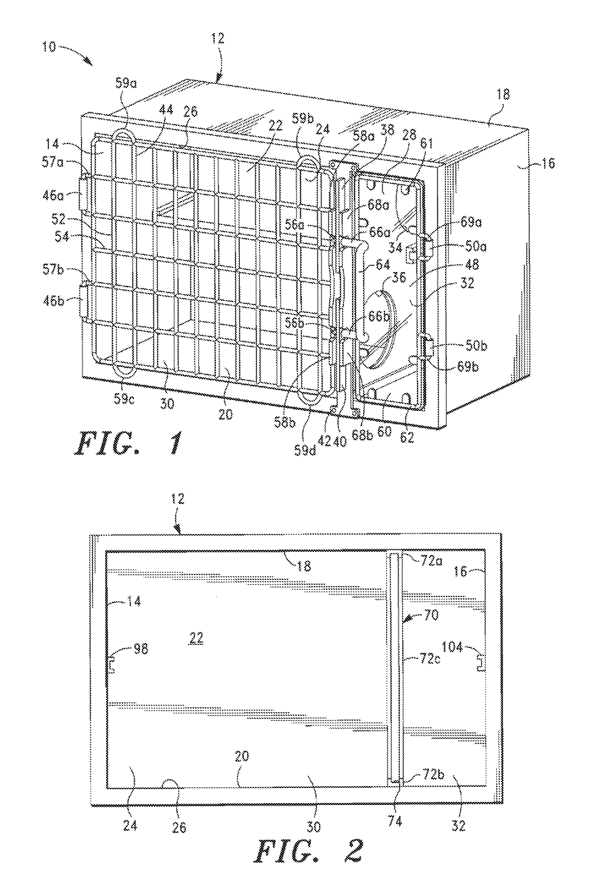
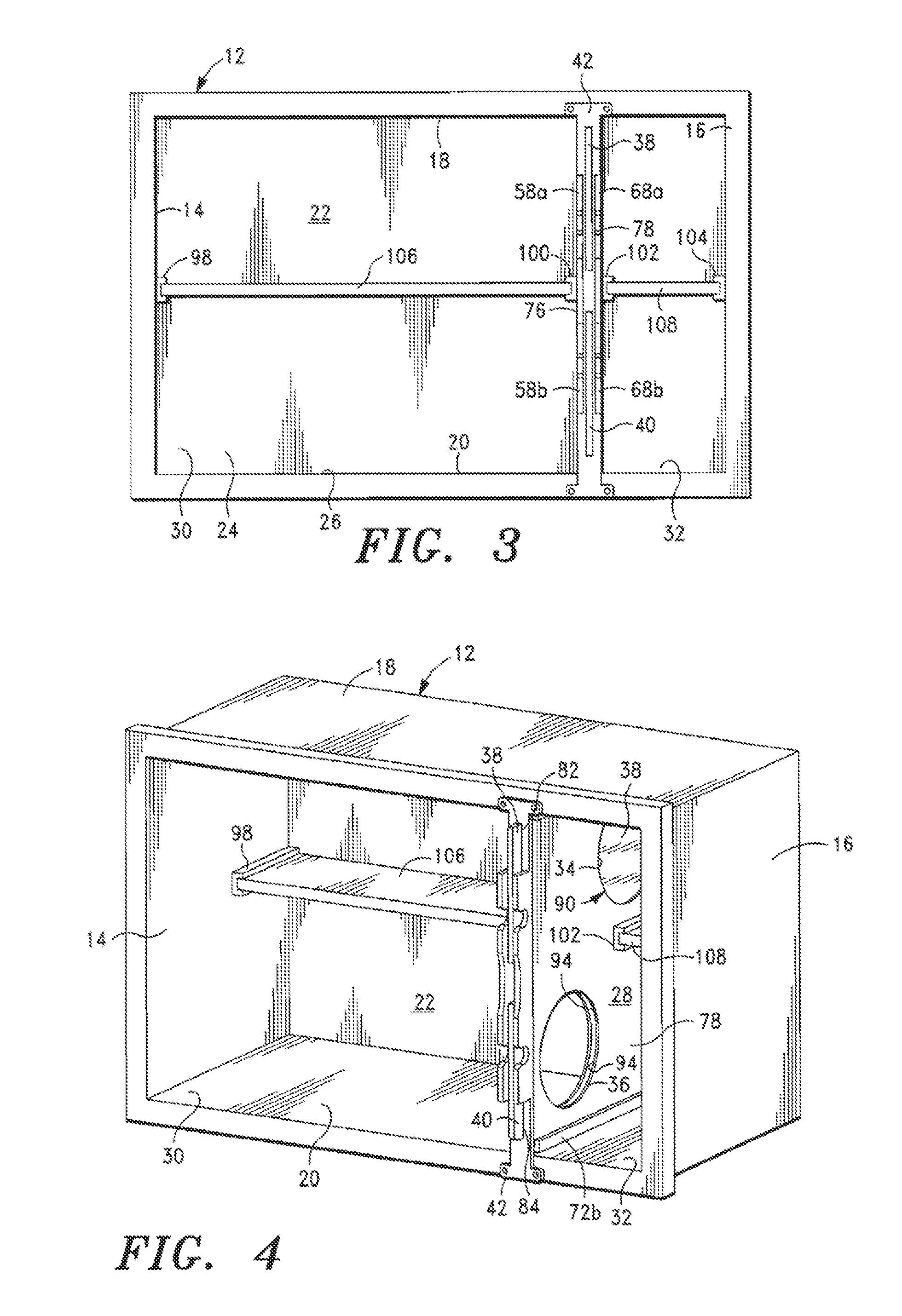
[0034]Referring now to FIG. 1, an animal cage according to one embodiment of the present invention is shown generally as 10. The animal cage 10 includes a housing 12 formed from side walls 14 and 16 that are joined with top, bottom, and rear walls 18, 20, and 22. The joined walls 14, 16, 18, 20, and 22 define an interior 24 of the housing 12, which is accessible via an opening 26 that is opposite rear wall 22. Looking to FIGS. 1, 4 and 5, divider 28 positioned within the interior 24 divides the interior into first and second chambers 30 and 32. There are upper and lower openings 34 and 36 in the divider 28 to allow an animal to move between the first and second chambers 30 and 32. As described below and shown in FIGS. 1 and 5, there are first and second door panels 38 and 40 that are slidable within divider 28 for regulating passage through upper and lower openings 34 and 36, respectively. A support member 42 is mounted to the front of the housing 12 between first and second chamber...


PUM


Abstract

An animal cage including a plurality of joined walls defining an interior and presenting a first opening for accessing the interior. A door that is mounted over the first opening is moveable between closed and open positions alternately limiting and allowing access to the interior. A divider is operable from outside the cage to removably engage at least one of the walls for dividing the interior into first and second chambers. The divider presents an opening for passage between the chambers. A door panel is supported by the divider and is moveable relative to the divider between a closed position blocking the opening in the divider and an open position allowing passage between the first and second chambers. The cage may comprise a cage run consisting of one or more elongated enclosures that can be divided with the removable dividers into a plurality of cage compartments.

Description

CROSS-REFERENCE TO RELATED APPLICATIONS[0001]Not Applicable.STATEMENT REGARDING FEDERALLY SPONSORED RESEARCH OR DEVELOPMENT[0002]Not Applicable.BACKGROUND OF THE INVENTION[0003]1. Field of the Invention[0004]The present invention relates generally to an animal cage, and more particularly, to an animal cage having a removable divider with door.[0005]2. Description of Related Art[0006]A variety of different animal cages are used by veterinarians, pet owners, pet stores, and animal care professionals to safely house and contain an animal or animals. Typical animal cages include a plurality of joined walls that enclose an interior space and a door for accessing the cage's interior. These cages are constructed out of various materials including steel, plastic, fiberglass and wood. Just as animals come in all different shapes and sizes, animal cages are built with various dimensions and sizes.[0007]The quandry for animal care professionals who see a variety of animals for a variety of rea...

Claims


Application Information

Patent Timeline
Patent Type & Authority Applications(United States)
IPC IPC(8): A01K1/03
CPCA01K1/03
Inventor MATTESON, MICHAEL L.DONAHUE, KARL J.
Owner SCHROER MFG
Why Eureka
Try Eureka